Has your D-160 (D-180) engine worked so many hours that there is no point in repairing it? So it’s time to replace the tractor’s “heart”!
How to quickly and inexpensively replace the engine of a T-170, T-130, B-10 tractor?
The answer to this question is known to regular customers of PromTorg LLC!
Our company supplies D-160, D-180 engines for T-170, T-130, B-10 tractors, produced by ChTZ. Prices for these products are available to everyone. Depending on the volume of supplies, we also provide discounts to regular customers.
Diesel engine cylinder block D-160
______________________________________________________________________________________________
Malfunctions of the D-160 cylinder block of the T-130 tractor (bulldozer) are cracks, holes, and flange breaks; thread failure in the block holes for studs and bolts; wear of beds - sockets for main bearing shells. Dismantling the D-160 cylinder block of the T-130 tractor
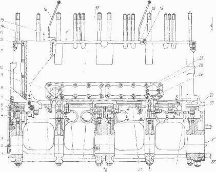
Fig.1. D-160 cylinder block assembly (side view) Remove the assembly units and parts attached to the block from the diesel engine, unscrew the studs 14 and 15 (Fig. 1 and 2) securing the cylinder heads. Fig.2. D-160 cylinder block assembly (front view) The liners of 13 cylinders are pressed out. Unscrew the nuts and remove the block cover 25 from its left side. Unscrew the bolts and remove the front and rear water jacket covers from the left side of the block. Unscrew the bolts, remove the inspection hatch covers 42 from the right wall of the block. Unscrew the fittings 39 and the bolts securing the clamps 18 and tubes 16 for supplying oil to the rocker shafts and remove the tubes. Unscrew fittings 6 and 30 and remove tubes 7, 3 and 5 for supplying oil to the main bearings. Unscrew fittings 4 from the block, nipples for attaching tube 3 for supplying oil to the balancing mechanism and remove the tube. Unscrew the nipples securing the oil supply tube 54 to the camshaft bearing and intermediate gear, and remove the tube. Unscrew elbows 7 and 51 and tee 2 from the front wall of the block. Remove tube 57 with rubber ring 56. Unscrew fitting 48 securing the main oil line 35, and then the intermediate fitting 45 from the wall of the block. Unscrew the castle nut 23 securing the main oil pipeline and unscrew it. Remove washer 22, spring 21 and oil line 35 from the stud and remove it from the block. Further disassembly of the D-160 cylinder block (pressing out pins 31, 36 and 41, oil seal 24, plugs 11, unscrewing pins 32 and 50) is performed if necessary. During subsequent repair operations, the caps of the main bearing supports must not be removed from the block or, if removal is necessary, they must be swapped, turned over, and depersonalized. To ensure the correct installation of the covers in their sockets, marks are placed on them and the end of the block socket - the letter “M”, the number and serial numbers of the main bearing supports in the engine. If necessary, press out the camshaft bushings using a stepped mandrel. Repair of the D-160 cylinder block The cylinder block of the D-160 diesel engine of the T-130 tractor (bulldozer) is made of SCh 20 cast iron. Blocks with kinks and cracks between the holes for the cylinder liners and in the lower walls of the crankshaft support bearings must be discarded. Cracks in the walls of the water jacket and crankcase space are sealed by welding with or without placing linings. The ends of the cracks are drilled with a drill with a diameter of 4 mm. The edges of the cracks are cut and welded with electrodes. Cracks are welded in sections. It is necessary to avoid overheating of the block and resume welding only after cooling the seam in the previous section to 40...50°C. Through cracks and broken flanges can be welded by cold electric arc welding with copper-steel and austenitic electrodes. Surfacing is carried out using separate beads, avoiding overheating of the base metal and applying the next bead 1...2 minutes after the end of surfacing of the previous one. The beds under the liners are restored by cold or hot (arc and gas) surfacing. Before surfacing, worn or damaged beds are bored by 0.3...0.4 mm. To avoid the appearance of cracks, the surface near the worn bed is heated to 500...700 °C. The deposited beds are bored using a boring bar with cutters on a special machine or universal device. Correct installation of the device's boring bar is ensured by two half-rings, which are installed in the bed of the outer bearings. For cylinder blocks of the D-160 engine of the T-130 bulldozer, in which the wear of the beds under the liners exceeds 0.05 mm, the installation of a boring bar is carried out using two specially made technological covers. When equipping the device with a mechanical drive, all beds are bored simultaneously. First, rough boring is carried out, leaving an allowance of 0.1 ... ... 0.3 mm per diameter. If the bore in the block for the cylinder liner collar has damage to the end surface or the difference in depth across four measurements is more than 0.07 mm, repair the end surface. It is performed on a radial drilling machine using a self-aligning countersink along the axis of the hole with an adjustable ring stop. An allowance of 0.2 mm is sufficient for processing. The difference in the boring depth after restoration when measured in four places around the circumference should be no more than 0.05 mm. When installing a cylinder liner in such a block, an additional gasket is placed under its collar so that the protrusion of the upper end of the liner collar above the plane of the block is within 0.07...0.33 mm. The repaired cylinder block of the T-130 tractor is subjected to a hydraulic test for the tightness of the water jacket under a pressure of 0.4 MPa; water flow and droplets on the walls are not allowed. The camshaft bushings are made of steel-aluminum strip with an anti-friction alloy. After being pressed into the block, the bushings are bored using a boring bar to ensure the alignment of the bored holes. Repair size bushings (front A57.02.001A, middle and rear (A.57.02.003A) have an internal diameter of 66.8 + 0.04 mm (with allowance for boring in the block). After boring the bushings, the center-to-center distance between their inner surface and the surface of the beds for the main bearing shells should be 242.25...242.30 mm. The diameter of the holes in the bushings for the new camshaft is 68 +0.03 mm. Assembling the D-160 cylinder block of the T-130 bulldozer When assembling the D-160 engine cylinder block, observe the following technical requirements. The lubrication system of the unit is washed under pressure, then pressurized with engine oil, heated to 60...70 °C, for 3 minutes with a pressure of 0.3 MPa; oil leakage through the connections is not allowed. For pressure testing, a mixture of 55% motor oil can be used oil and 45% diesel fuel.The water cavity of the block assembled with the liners is subjected to a hydraulic test under pressure of at least 0.4 MPa for at least 3 minutes; water leakage and drop formation, as well as water flow through the cylinder liner seals, are not allowed. The studs securing the main bearing caps are tightened to failure; tightening torque 150…250 Nm. After tightening the fastening nuts, the main bearing caps should fit snugly along the joint planes to the block. The 0.03 mm feeler gauge should not fit into the joint between mating parts. A probe with a thickness of no more than 0.08 mm is allowed to enter between the block and the bearing caps to a depth of no more than 10 mm due to the permissible deviation from the flatness of the mating surfaces. Before assembly, the D-160 block is cleaned of contaminants, the oil supply channels are washed and blown with dry compressed air. Clean the water jacket of the unit from scale. Press bushings 33 (see Fig. 1 and 2) of the camshaft into the holes of the block. Cylinder liners are selected according to size groups. It is recommended to install sleeves of the same groups in the block. Place the block sleeves and rubber sealing rings 5, lubricating them with red lead; Copper rings 12 are placed under the sleeve collar and the sleeves are pressed into the block. Pre-lead chamfers of the sockets are lubricated with diesel oil. Install the cylinder block of the D-160 engine of the T-130 tractor on the stand with the main bearing caps facing up. Clean the hole for plug 29 and press it into the socket. Install plug 55 into the block, plugging the hole going to the channel for supplying oil to the timing gear. Plug the hole in the oil supply channel to the small intermediate gear with pin 44. Lubricate the threaded part of the stud 20 securing the main oil line with red lead and screw it completely into the hole of the block from the inside. Install oil line 35, spring 21, washer 22 on the stud in sequence, screw on nut 23 and lock it with a cotter pin. Place ring 49 on the intermediate fitting 45 for fastening the main oil line and screw the fitting into the threaded hole of the block. The oil line mounting fitting 48 with ring 27 is inserted into the intermediate fitting 45, the second ring 27 is put on and the fitting is screwed into the oil pipe elbow. Screw six fittings 4 into the threaded holes of the main bearing supports. Connect the front tube 37 from the middle main bearing, three tubes 38 from the second, third and fourth main bearings, tube 34 from the fifth main bearing, tube 40 from the first main bearing to the main oil line and the cylinder block. bearing and attach all the tubes to the block and the oil pipeline with fittings 6 and 30, laying the O-rings. To ensure sufficient lubrication of the first main and connecting rod bearings, fittings 6 have a larger flow area than fittings 30, so they are not allowed to be swapped during assembly. Install two tubes 16 for supplying oil to the rocker shafts on the main oil line and secure them with fittings 39, having previously laid the O-rings. The tubes are secured with clamps 18 with locking plates 19 and bolts on the upper plane of the block. The ends of the locking plates are bent at the edge of the bolts. When installing tubes before hydraulic testing, it is allowed to bend them in place to ensure the necessary clearances between the tubes and the rotating crankshafts and camshafts, block walls and other parts. Screw elbow 55, two elbows 51 and tee 2 into the threaded holes on the front wall of the block. Install oil supply tube 54 to the camshaft and intermediate gear bearings, connecting the tube nipples with elbows 51 and 55. Install oil supply tube 3 to the balancing mechanism, connecting one tube nipple with a tee, screwing the other into the end of the main oil pipeline. The tubes must not touch the block wall. Install tube 47 for oil supply to the fuel pump regulator with rubber ring 46 put on it in the right wall of the D-160 cylinder block of the T-130 bulldozer.
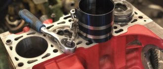
Place a rubber ring 56 on the copper tube 57 for supplying oil to the oil pump drive intermediate gear and insert it into the hole on the front wall of the block. For further assembly, turn the block upside down with the surface on which the heads are located. Install the front cover 7 with two studs 9 and the rear cover 26 with gaskets 52 on the left side surface of the block. The covers are secured with bolts and spring washers. Gasket 28 and cover 25 are installed on the back cover, securing it with two nuts and spring washers. Place inspection hatch covers 42 with gaskets 43 on the right wall of the block. The covers are secured with bolts and spring washers. Screw the pins 14 and 15 of the block head fastening into the upper plane of the block until it is tight; the tightening torque of the studs is 150...200 and 60...80 Nm, respectively. Press the oil seal 24 with the working edge of the cuff into the block. Diesel cylinder liners D-160 Typical malfunctions of the cylinder liners of the D-160 engine are wear along the internal diameter, deviation from the flatness of the lower end of the support shoulder, chips and cracks. When removing the liner, drain the oil from the crankcase and water from the cooling system. Remove the piston and connecting rod. The crankshaft journals are covered to protect them from damage and from foreign particles getting into the channels. Remove the cylinder liner from the block. The block sleeve is made of manganese cast iron, its inner surface is hardened with high-frequency heat to a depth of at least 1.6 mm to a hardness of 42. Sleeves with cracks and chips are subject to rejection, sleeves that do not have these defects are checked for leaks with a hydraulic pressure of at least 0.4 MPa . If the pressure drops within 2 minutes after stopping the liquid supply, the sleeve is rejected. It is allowed to test the cylinder liner of the T-130 tractor for leaks by immersion in liquid and supplying air with a pressure of at least 0.4 MPa for 3 minutes; bubbles are not allowed. Worn cylinder liners along the inner diameter are restored by boring, honing and polishing to a repair size of 145.7 + 0.08 mm for repair pistons and piston rings increased in outer diameter by 0.7 mm. If the equipment is available, the cylinder liner is processed along the inner diameter using the method of preliminary power honing, followed by finishing honing and polishing. The liner to be repaired is pre-processed in two passes with honing stones 225x12x6x4 mm to a diameter of 145.60+0.04 mm and a diameter of 145.67+0.04 mm. Wear, nicks, dents at the ends of the liner support collar, increased end runout relative to the internal diameter (more than 0.03 mm) are eliminated by processing on a diamond turning machine. The thickness of the collar after processing should be 13.12-0.07 mm. Then fine honing is carried out with stones to a diameter of 145.7 + 0.075 mm. The repaired cylinder liner of the D-160 diesel engine must satisfy the following technical requirements: - the ovality and taper of the internal polished surface in the area located 27 mm from the upper end and 270 mm long must be no more than 0.025 mm; — the runout of the lower end of the support collar relative to the inner surface of the liner should be no more than 0.030 mm. When testing for paint, a contact patch on the lower end of the support collar is allowed to be at least 2 mm wide, closed around the circumference; - porosity is allowed on the inner surface resulting from chipping of graphite and the metal base along the boundaries of graphite inclusions during mechanical processing, as well as clean gas shells in the largest dimension of no more than 1 mm and a depth of no more than 1 mm in an amount of no more than 3 pieces located at a distance of at least 30 mm from one another. On areas of the inner surface of the liner of the D-160 cylinder block, spaced no more than 20 mm from the upper end and 80 mm from the lower end of the liner, the presence of clean gas shells along the largest dimension of no more than 2 mm and a depth of no more than 1 mm in an amount of no more than 3 is allowed. pcs., located one from another at a distance of at least 30 mm. In a section 20 mm long from the upper end of the liner, shrinkage porosity with an area of no more than 1 cm2 is allowed, with the largest pore size up to 1 mm. When installing repaired liners in a block, it is necessary to place an additional ring under the collar to compensate for the trimming of its end to ensure that the lower support shoulder protrudes above the plane of the block within 0.070 ... 0.330 mm. Repaired cylinder liners (0 145.7 + 0.08 mm), as well as new ones (0 145 + 0.08 mm), are sorted into four size groups according to the smallest internal diameter. The size group index is stamped on the upper end of the sleeve. Before installing the liners, clean the seating surfaces in the cylinder block and liners. Then put the copper ring on the upper belt of the sleeve. After this, insert the sleeves (without rubber rings) into the holes of the block and press them into the block. Check the size, ovality and taper of the inner surface of the liner in a section 270 mm long, spaced 27 mm from the upper end of the liner. It is allowed to repress the liner into the block and rotate it to ensure the specified ovality and conicality of the inner surface. Check the protrusion of the liner flange of the D-160 diesel cylinder block above the plane of the block using a device with an indicator at four points around the liner. The protrusion height should be 0.07 ... 0.33 mm. The difference between four diametrically opposite measurements should not exceed 0.08 mm. The difference in the protrusions of liners pressed by one cylinder head is allowed no more than 0.08 mm. Rotating the liner in the block can change the height of its protrusion above the block, the ovality and taper of the inner surface. If the height of the liner protrusion exceeds the limits of 0.07 ... 0.33 mm, check the thickness of the liner collar, the thickness of the copper gasket and the boring depth in the cylinder block. Thickness A (Fig. 3) of the sleeve collar should be 13.2+0.075 mm; depth B of the bore in the cylinder block is 14+0'07 mm; Thickness B of the copper gasket is 1_0.08 mm. Fig.3. Checking the dimensions in detail to ensure the required protrusion of the end of the D-160 cylinder liner of the T-130 tractor above the plane of the block. By selecting another copper gasket or liner, the required protrusion height above the block is ensured. After this, marks are applied to the ends of the sleeve and the block to install the sleeve in its previous position. Remove the sleeve from the block. Install new rubber seal rings into the grooves of the liners. The rings must be elastic, without damage, not twisted and protrude from the grooves of the sleeve by 1.5 ... 2.5 mm. Lubricate the lower seating belt of the sleeve and the sealing rings with red lead. Install the sleeves into the block using a device, aligning the marks on the ends of the sleeves and the block during installation. Check, as indicated above, the ovality and conicality of the inner surfaces of the liners.
______________________________________________________________________________________
___________________________________________________________________________________________
Other special equipment
MTZ-80
- Creeper MTZ-80, 82
- Design of the chassis of the MTZ-80 tractor
- Gearbox MTZ-80
- Clutch MTZ-80, 82
- Maintenance and adjustment of the MTZ-80.82 gearbox
- Starting motor PD-10
- Transfer case MTZ-80
- Adjustments of drive axles MTZ-80, 82
- Steering gear and power steering MTZ-80, 82
- Braking system MTZ-80, 82
- PTO MTZ-80, 82
______________________________________________________________________________________
YaMZ-236
- Components of the YaMZ-236 HE2, BE2 cylinder block
- Clutch YaMZ-181,182,183
- Clutch discs YaMZ-236, 238
- Crankshaft and piston group YaMZ-236
- Gearbox YaMZ-236
- Diagnostics and adjustment of the YaMZ-236 engine
- Fuel supply and lubrication of the YaMZ-236 diesel engine
- Clutch YaMZ-236
- Injection pump and injectors YaMZ-236
YaMZ-238
- Cylinder block and piston group YaMZ-238
- Crankshaft and timing belt of diesel engine YaMZ-238
- Gearbox YaMZ-238
- Cooling and lubrication of diesel engine YaMZ-238
- Clutch YaMZ-238
- Fuel injection pump YaMZ-238
T-130
- Onboard clutches T-130
- Final drive T-130
- Diesel D-160 tractor T-130
- Undercarriage T-130
- Turning mechanism of the T-130 tractor
- Assembly and installation of T-130 trolleys
- Servomechanism of onboard clutches T-130
- Tractor clutch T-130
- Control mechanism for clutch and mountain brake T-130
T-170
- D-180 engine of T-170 bulldozer
- Hydraulic system of bulldozer T-170
- Hydraulic cylinder of bulldozer T-170, 130
- Repair of the main gear of bulldozer T-170, 130
- Tracks and rollers T-170, 130
- Carrying and running system T-170
- Assembly of gearbox units T-170, 130
- Tension mechanism and support roller T-170, 130
- Bulldozer equipment T-170 with rotary blade
- Adjusting the T-170 clutch
- Transmission parts for bulldozer T-170
KRAZ
- Gearbox KRAZ-255, 260
- Steering of Kraz-250, 255
- Drive axle and cardan shafts Kraz-255, 260
- Clutch Kraz-250, 260
- Power steering of the Kraz car
- Kraz car suspension
- Kraz transfer case
- Kraz power take-off
- Brake system for Kraz-6510, 65055 vehicles
- Cardan transmission and drive axles Kraz-6510, 65055
- Front suspension of Kraz-6510, 65055 cars
- Steering KRAZ-6510, 65055
- Clutch Kraz-6510, 65055