Payment for goods and downloading of the book in electronic form (PDF format) is made on the website.
To do this, you need to find the book you are interested in and click on the “Buy” button. The price of the book is indicated on the button.
For convenience, the price on the website for residents of Russia, Belarus and Kazakhstan is presented in rubles.
For residents of Ukraine in hryvnias, and for all other countries - dollars.
After clicking on the “BUY” button, a payment window will open where you can select a payment system with which you can pay for the selected book using any bank card (Visa, MasterCard, MIR, etc.)
When you click on the “Pay by bank card” button, the Portmone payment system will open, which is the easiest way to make a payment.
In addition, the website offers four payment systems for payment:
- Yandex (payment from any bank cards, Yandex Money account, QIWI Wallet, terminals, etc.);
- Portmone (payment from any bank cards, Portmone account);
- PayPal (payment from any bank cards, PayPal account);
- WebMoney (payment from any bank cards, payment from WebMoney wallets).
Payment via Yandex Cashier
After selecting payment via Yandex, the Yandex Cashier payment system will launch, where you need to select a convenient payment method (bank card, QIWI, Yandex Money account, etc.)
After specifying payment details and confirming payment, payment for the goods will occur.
If you have a bank card in a currency other than the ruble, then the money will be debited from the card at the rate of the Central Bank of Russia at the time of the purchase.
This payment method is optimal for residents of Russia, Kazakhstan and Belarus.
Official website of the Yandex Kassa payment system https://kassa.yandex.ru
Payment via Portmone
After selecting payment through Portmone, the payment system will launch, where you need to select the payment method: bank card or Portmone account.
The price in the Portmone payment system is converted into dollars at the exchange rate of the Central Bank of the country where you are located.
If you have a bank card in a currency other than the dollar, then the money will be debited from the card at the rate of the Central Bank of your country at the time of the purchase.
After specifying payment details and confirming payment, payment for the goods will occur.
Official website of the Portmone payment system https://www.portmone.com
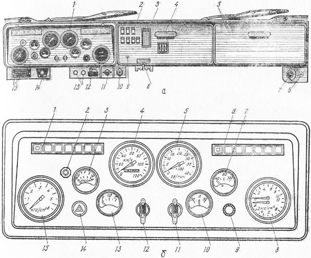
KAMAZ instrument panel
On the KAMAZ dashboard
(see Fig. KAMAZ instrument panel) are located:
- dashboard;
- switch panel containing:
- key switches and switches;
- PTO or winch PTO switch button;
- electromechanical headlight leveler, the handle of which adjusts the light beams of the headlights depending on the load;
- rotary knob - a switch that controls the autonomous cabin air heater (for vehicles equipped with an autonomous cabin heater). The rules for using the heater are set out in the Autonomous Heater Operation Manual supplied with the vehicle. Connection diagrams for autonomous heaters Planar f. "ADVERS" and Air Tor f. "WEBASTO" are presented in Fig. Electrical diagram for connecting the cabin heater Planar f. "ADVERS", Electrical diagram for connecting the cabin heater Air Tor f. "WEBASTO"; control lamps. When you pull the switch panel towards you, access to fuses and relays opens (see section “Electrical equipment”).
- glove box.
On additional panels located under the main instrument panel, the following are installed:
- heater and cabin ventilation control levers. Use the upper lever to turn on and regulate the heating of the air coming from the heater, and use the lower lever to control the distribution of this air in the cabin. In the extreme right position of the lower arms, air is supplied only to the windows; in the CABIN position, air is supplied to the windows and the feet of the driver and passenger. Intermediate positions allow you to change the heating efficiency. Turning on the air supply - with the key switch of the heater electric motor on the switch panel when the keys are in position I and II in the instrument and starter switch lock;
- engine stop handle. The handle is recessed - the engine is ready to start; To stop the engine, pull out the handle; — manual fuel supply control handle;
Depending on the vehicle configuration, the engine stop handles and manual fuel control handles are installed on the instrument panel (see Fig. Instrument panel) or to the right of the driver’s seat;
- control lever for locking the center differential of the transfer case;
- control lever for locking the center differential of the axles. The lock is engaged in the SLIPPERY ROAD position;
- radiator shutter control handle (not available on vehicles equipped with charge air cooled engines). When the handle is extended, the blinds are closed;
- transfer case control valve handle;
- tire pressure control valve lever.
KAMAZ instrument panel
1 — instrument panel; 2 — switch panel; 3 — PTO or PTO winch switch button; 4 — electromechanical headlight range control; 5 — control levers for the heater and cabin ventilation; 6 — engine stop handle; 7 — transfer case control valve handle; 8 — control lever for locking the center differential of the axles; 9 — handle for manual control of fuel supply; 10 — control lever for locking the center differential of the transfer case; 11 - radiator shutter control handle (for vehicles with an engine without ONV); 12 — lever of the tire pressure control valve (if there is a centralized tire inflation system); 13 - rotary knob - switch (for vehicles equipped with an autonomous cabin heater); 14 - warning lamps
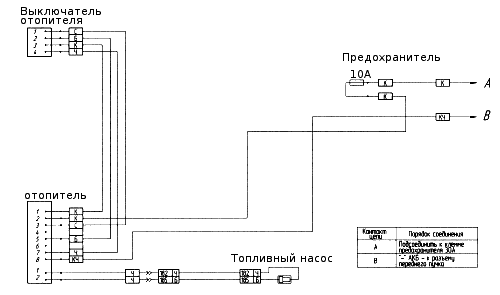
Electrical diagram for connecting the cabin heater Air Tor f. "WEBASTO"
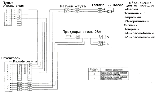
Electrical diagram for connecting the autonomous cabin heater Planar f. "ADVERS"
Payment via PayPal
After selecting payment via PayPal, the PayPal payment system will launch, where you need to select the payment method: bank card or PayPal account.
If you already have a PayPal account, then you need to log into it and make a payment.
If you do not have a PayPal account and you want to pay using a bank card via PayPal, you need to click on the “Create an Account” button - shown with an arrow in the picture.
PayPal will then prompt you to select your country and provide your credit card information.
After specifying the information required to make the payment, you must click on the “Pay Now” button.
Official website of the PayPal payment system https://www.paypal.com
Payment via WebMoney
After selecting payment via WebMoney, the payment system will launch, where you need to select the payment method: bank card or WebMoney wallet.
If you already have a WebMoney wallet, then you need to log into it and make a payment.
If you do not have a WebMoney wallet and you want to pay in another way, you need to select any of the methods that WebMoney offers and make the payment
After specifying payment details and confirming payment, payment for the goods will occur.
Official website of the WebMoney payment system https://www.webmoney.ru/
What can a colored electrical diagram of KamAZ 65115 tell you?
The electrical network of any vehicle, including KamAZ 65115, is responsible for the functionality of all its electrical devices and systems, connecting them together and ensuring the interaction of many components. The KamAZ 65115 electrical circuit, color or black and white, allows you to understand this complex network.
It indicates all the electrical elements involved in the operation of vehicle systems and which are possible causes of certain problems. The ability to read this diagram and analyze the operation of certain components can play an important role in the process of car repair and maintenance.
Electrical diagram of the KamAZ 65115 car
It is clear that the more preferable option in terms of convenience and information content is the KamAZ color electrical diagram, in which the color of the cables used in the standard electrical wiring is reflected by the corresponding color of the lines. In addition, this image shows in schematic form all devices, sensors and components operating from the vehicle’s on-board network.
All KamAZ trucks, including the model 65115 in question, are equipped with a number of electrical subsystems. Specifically, the machine utilizes electrical systems that provide the following functions and capabilities.
- Starting the propulsion system.
- Functioning of the heating system, windshield wiper and power supply system.
- Lighting fixtures inside the car interior.
- Lighting, including high and low beam lights, fog lights, side lights, brake lights, turning lights and hazard warning lights.
- The instrument panel, which is one of the main components of the on-board electrical network due to the concentration of most sensors, instruments and devices, including the speedometer, tachometer, fuel gauge and many others. It is the instrument panel that is equipped with various indicators that light up when the lights are turned on, the hand brake is activated, and in other situations, and allow the driver to indirectly assess the condition of certain systems and units.
- Functioning of the anti-theft system and multimedia system.
- The operation of the fuse box, which is responsible for preventing problems in the operation of electrical networks in the event of voltage surges. The mounting block includes a number of fuses that ensure the functionality of all critical electrical systems.
- A control unit responsible for the full functioning of various electrical equipment.
To ensure normal operation of the KamAZ 65115 electrical system, the vehicle's electrical wiring must be in a condition no worse than satisfactory. In addition, the health of a number of electrical system components, including batteries, plays a very important role.
The KamAZ vehicle uses two batteries connected in series, the positive output of which is connected to the starter connector, and the output with a minus sign is connected to the truck body through a switch.
The batteries, located in a box located on the frame of the car behind the cab, ensure the functionality of the ignition during engine starting, as well as the ability to operate various electrical equipment when the engine is stopped.
The KamAZ electrical circuit is not capable of functioning normally without such an important link as a generator. It provides power to electrical components and devices when the engine is running. In addition, it is the generator unit that charges the batteries.
Troubleshooting
In case of failures and malfunctions in the operation of the vehicle's electrical circuit, self-diagnosis can be performed in several different ways, for the implementation of which the KamAZ wiring diagram is also useful.
In particular, the simplest types of testing may include checking the presence of voltage in a particular section of the circuit using a multimeter or other indicator.
In general, diagnosing problems in the operation of an electrical circuit involves a certain sequence of actions.
First of all, one of the contacts of the test lamp or tester is connected to the negative terminal of the battery, the second to the connection of the circuit section being tested. It is recommended to try to make the connection as close as possible to the battery or a nearby fuse.
The appearance of a voltage value on the multimeter screen or the inclusion of an indicator light means the normal operation of the tested area, that is, that all elements are connected correctly and there is no need to carry out repairs.
In this case, one should take into account the fact that the voltage in individual circuits is maintained only at a certain position of the ignition key in the lock.
The remaining sections of the electrical circuit are checked in the same way. Identifying a point where there is no voltage most often means that the source of the problem is located between it and the last good part of the system. Problems with electrical wiring on KamAZ 65115 Euro 2 vehicles and other models and modifications are most often caused by poor contact.
In addition, you can try to independently determine the presence of a short circuit. Having removed the corresponding fuse from the circuit, a voltmeter is connected to the free terminals with one probe. Having first made sure that all components of the circuit being diagnosed are de-energized and disconnected, move the connected wire
If changes in the position of the wire cause values to appear on the screen, we can conclude that there is a short circuit, most often resulting from a frayed insulating braid of the cable.
Downloading a book
After successfully completing the payment (by any method) and returning to the KrutilVertel store from the payment system website, you will be taken to the successful payment page:
On this page you need to indicate your e-mail, where access to download the book will be sent.
If you are already registered on our website, then simply follow the link to your personal account.
The book you purchased will be in your personal account, from where you can always download it.
Please note that after making the payment, you need to return back from the payment system website to the KrutilVertel website.
If for some reason you did not return back to the site and closed the payment system tab with a message about the successful completion of the payment, please let us know - we will send you a letter indicating access to download the book.
Description of indicators on the KAMAZ instrument panel (65115, 43118 and 5320): combination and repair
In the driver's cabin you can find many incomprehensible devices, the purpose of which must be explained for the correct operation of the vehicle.
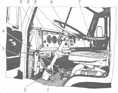
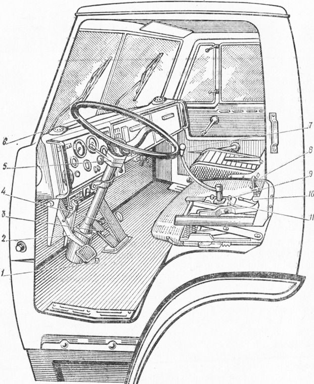
Each of these devices is located on a special panel, which folds back and is located on the left side of the panel. The first device where the eye falls is the steering wheel. It is located in the picture below at number 6 and makes it convenient to monitor the readings that are displayed on the measuring instruments in the cockpit. Thanks to the figure below, you can find out the purpose of each button, pedal and lever that are located in the driver’s cab.
Purpose of instruments in the driver's cabin
- Auxiliary (direct) brake control button.
- The pedal is responsible for the clutch.
- A pedal responsible for controlling the brake valve.
- A pedal that controls the start of fuel.
- Air pressure distributor.
- Steering wheel.
- Windshield cleaning device.
- Window lift system lever.
- Gearbox control knob.
- Handle for closing the door.
- Handle for longitudinal movement of the passenger seat.
- Lever for adjusting the backrest of the passenger seat.
- Driver's seat suspension stiffness control lever.
- Engine cable.
- Valve handle for parking and emergency brakes.
- A device that fixes the adjustment of the backrest angle of the driver's seat.
- Fuel supply thanks to manual control.
- The handle responsible for the function of longitudinal movement of the driver's seat.
- Cabin fairing.
Instrument cluster
Below is how to diagnose problems in advance, as well as the most common breakdowns, including those due to improper use of the cigarette lighter.
KAMAZ blue
This review from the author of TheVostok98 is dedicated to the KAMAZ 5320 model.
CONTROLS, CAB EQUIPMENT AND INSTRUMENTS
The location of the controls is shown in Fig. 1.
— auxiliary brake button; — clutch pedal;
— pedal of the service brake system;
— fuel pedal;
— gear shift lever. The gear divider control switch is built into the lever handle. The switch can be used to select a higher or lower gear in the divider;
- instrument and starter switch with anti-theft device.
O - everything is turned off;
I - circuits of control and measuring instruments are turned on;
II - the circuits of instrumentation and starter are turned on, the position is not fixed;
In some vehicle configurations, an instrument switch with an anti-theft device is installed on the steering column. A description of the switch for devices with an anti-theft device is given in the Anti-theft device section.
— Combined light switch (see Fig. 2);
— manual fuel supply control handle;
- engine stop handle.
The handle is recessed - the engine is ready to start; To stop the engine, pull out the handle;
— control valve for parking and spare brakes.
Read further: Signs of a MAF MAF: how to check the mass air flow sensor with a multimeter and other methods, self-cleaning and replacing the device
The crane handle has two fixed positions: vertical—the parking brake is on, horizontal—the parking brake is off. In intermediate positions, the tractor and trailer are braked with a spare brake.
I — right turn indicator is on; 0 - everything is turned off; II — right turn indicator is on (non-fixed); A - first windshield wiper speed; III — left turn indicator is on (non-fixed); B - second windshield wiper speed; IV - left turn indicator is on; C - intermittent operation of the windshield wiper; V - high beam flashing; D — windshield washer switched on (non-fixed); VI — high beam is on.
Dashboard
- a switch panel on which key switches and switches, an ashtray, a radio receiver and a ground switch are located. When you pull the panel towards you, access to the fuses of electrical equipment opens;
— radiator shutter control handle. When the handle is pulled out, the blinds are closed.
— control lever for locking the center differential. The lock is engaged in the SLIPPERY ROAD position.
— control levers for the heater and cabin ventilation.
Use the upper lever to turn on and regulate the heating of the air coming from the heater, and use the lower lever to control the distribution of this air in the cabin. In the extreme right position of the lower arms, air is supplied only to the windows; in the CABIN position, air is supplied to the windows and the feet of the driver and passenger. Intermediate positions allow you to change the heating efficiency.
Turning on the air supply is a key switch on the fuse panel when the key is in position I and II in the instrument and starter switch lock.
In the case of delivery of vehicles with heater 15.8106, a control panel for the heater 15.8106 is installed above the instrument panel, see Figure 4. The control panel displays the operating status of the heater.
Rice. 3. Instrument panel
Rice. 4. Heater control panel 15.8106
Dashboard
— engine oil pressure indicator with a built-in warning lamp, which lights up when the pressure in the lubrication system drops to 39.78 kPa (0.4.0.8 kgf/cm2). The oil pressure in a warm engine should be 392.3. 539.4 kPa (4.0 - 5.5 kgf/cm 2 ) at the rated engine speed and not less than 98.1 kPa (1.0 kgf/cm 2 ) at the minimum speed;
— fuel level indicator in tanks with a built-in warning lamp, which lights up when the fuel in the tank decreases to 30 liters;
— liquid temperature indicator in the cooling system with a built-in warning lamp, which lights up when the coolant temperature rises above 98 ° C; normal coolant temperature is 80..98°C.
Read more: Active subwoofer under the seat: how to choose
— speedometer with total mileage counter of the car. Has a blue lamp that lights up when the high beam headlights are turned on;
— tachometer. When the car is moving, the tachometer needle should be on the right side of the green field. When the engine loses power, fuel consumption increases - the arrow is in the black field. The needle should not enter the red fields - these are dangerous modes for the engine!
- pressure gauge. The upper arrow shows the air pressure in circuit I, the lower arrow in circuit II of the pneumatic brake drive; nominal air pressure in the pneumatic drive (6.5. 8.0 kgf/cm 2 );
— instrument panel lighting switch. Turns on and regulates the level of illumination of devices;
- hazard warning switch. When you press the button, all direction indicators light up intermittently, as well as the warning light built into the handle;
— electric torch device (EFD) switch button. When you hold the button pressed for some time, the lamp in the control lamp block should light up, indicating that the ECU is ready to start the engine;
- remote power switch button;
— blocks of warning lamps;
Rice. 5. Instrument panel
— button for checking the serviceability of the warning lamps;
— control signal that the ECU is ready for operation, red;
— control signal for the vehicle’s direction indicators, green, intermittent;
— control signal for the trailer direction indicators, green, intermittent;
— control signal for turning on the cross-axle differential lock, red;
— warning signal about a clogged air filter, red;
— oil filter clogged warning signal, red;
— warning signals about a drop in pressure in the cylinders of circuits 1, 2, 3 of the pneumatic brake drive, red, a buzzer sounds when turned on;
— control signal for turning on the parking brake, red, intermittent.
Switches and key switches are shown in Figures 3 and 5.
— heater electric motor switch;
— rear fog lamp switch;
— fog light switch;
— platform lift/lower switch;
— mirror heating switch;
— wheel lock switch;
The order of switches and switches may be changed depending on the specific vehicle configuration.
Rice. 6. Warning lamp block
The KAMAZ instrument panel is often unclear and extensive. The purpose of each button and, in general, all the parts located on the instrument panel is important for each driver of the vehicle to know. Read more about this below in the article.
Content
[ To uncover]
[Hide]
Overview of the interior and controls of KAMAZ 65221)))
Cabin structure of KamAZ 43114
Steering of Kamaz 4310 and Kamaz 5320 vehicles
Gearbox on a Kamaz car (switching diagram) for subscribers
KAMAZ 43101 CONTROL-INSTRUMENTS
How to properly use a divider on a Kamaz
Read more: Description of a cable-driven gearbox: photo and video review
Everyday life of KAMAZ drivers: Lifting the body and the sound of the v8 engine
Review of KAMAZ 5320 (watch to the end)
Testers: KamAZ-6520
KAMAZ instrument panel assembly
Flatbed cab KAMAZ 5320, orange
KAMAZ Euro-3 instrument panel assembled.
How to untie KAMAZ.
KAMAZ dashboard
Cabin of KAMAZ concrete mixer truck, gray
KAMAZ 65115
Cabin KAMAZ 4310, KHAKI color
Test drive KAMAZ
Kamaz 5320 reviewer
Problems when paying with bank cards
Sometimes difficulties may arise when paying with Visa/MasterCard bank cards. The most common of them:
- There is a restriction on the card for paying for online purchases
- A plastic card is not intended for making payments online.
- The plastic card is not activated for making payments online.
- There are not enough funds on the plastic card.
In order to solve these problems, you need to call or write to the technical support of the bank where you are served. Bank specialists will help you resolve them and make payments.
That's basically it. The entire process of paying for a book in PDF format on car repair on our website takes 1-2 minutes.
If you still have any questions, you can ask them using the feedback form, or write us an email at [email protected]
Our advantages:
Professionalism:
Car repairs are carried out by highly qualified specialists with many years of experience in diagnosing and servicing Trucks and buses.
Speed:
Truck and bus repairs are carried out as quickly as possible; we have modern equipment and experienced personnel at our disposal.
Price:
We provide discounts on repairs of Trucks and buses to regular customers.
Quality:
Car repairs are performed by experienced, qualified specialists. Availability of certificates for all types of work.
Guarantees:
The guarantee applies to all types of work.

