4.1.1. Steering repair. Power steering
Rice.
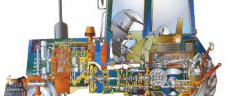
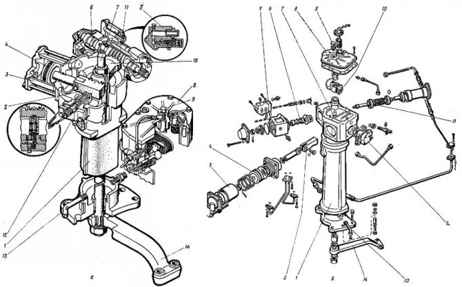
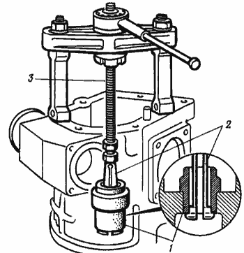
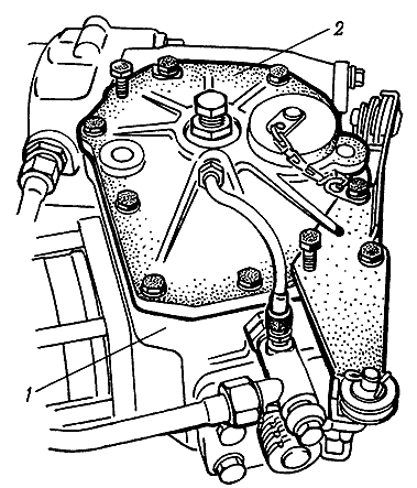
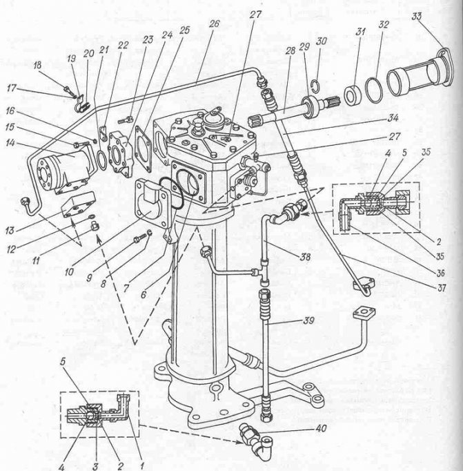
2.3.10. Power steering (power steering): a - general view; 1 - amplifier housing; 2 - rail; 3 — power cylinder; 4 - piston; 5 - safety valve; 6 — spool; 7 - rotary shaft; 8 — upper cover of the power steering housing; 9 — adjusting bolt of the rotary shaft; 10 - sector; 11 — worm of the steering mechanism; 12 — differential lock sensor; 13 — drain pipe; 14 — steering bipod. The main defects of the power steering include: wear of the worm shaft splines and sector teeth, gear rack, wear and violation of the tightness of the safety valve, wear and violation of the hydraulic tightness of precision parts (spools, plungers, sleeves). If, in the process of checking the technical condition of the units of the hydraulic steering control system of the tractor, faults are identified that cannot be eliminated by carrying out normal adjustment operations, the power steering is removed from the tractor and disassembled for technical examination and replacement of parts. The sequence of basic operations and the correct techniques for disassembling, assembling and adjusting the power steering are shown in Fig. 2.3.9 - 2.3.30.
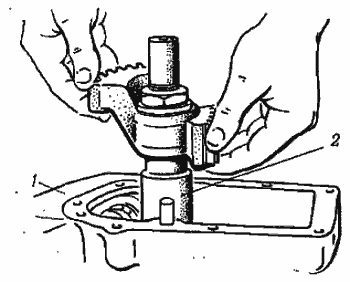
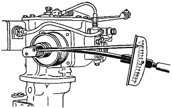
Before removing the power steering, drain the hydraulic fluid and unscrew the steering shaft nut 4 .
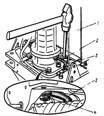
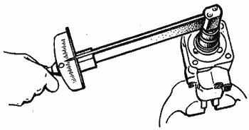
Rice. 2.3.9. Compressing the steering bipod: 1 - extension; 2 — steering bipod; 3 - drain pipe; 4 — rotary shaft nut.
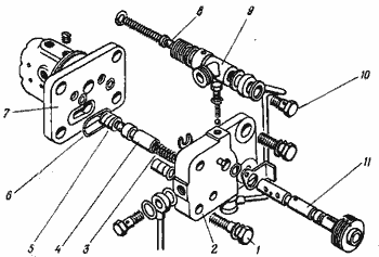
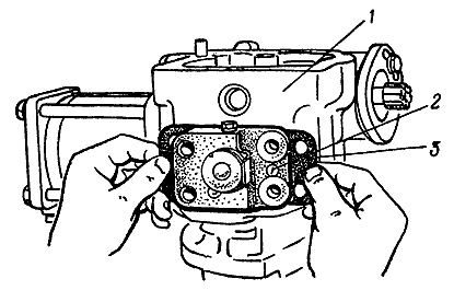
Rice. 2.3.11. The relative position of the differential lock sensor parts: 1, 10 - bolts; 2 - cover; 3 - spring; 4 - spool; 5 - pusher; 6 - ring; 7, 9 — housings; 8 - valve; 11 - tap.
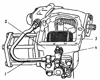
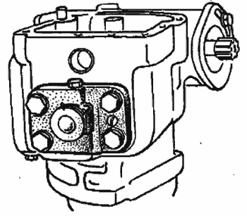
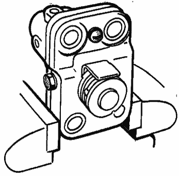
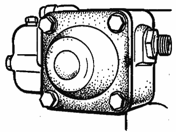
Rice. 2.3.12. Removing the oil supply tube from the distributor: 1 - oil supply tube; 2 — power steering housing; 3 - mesh filter; 4 - pressure reducing valve.
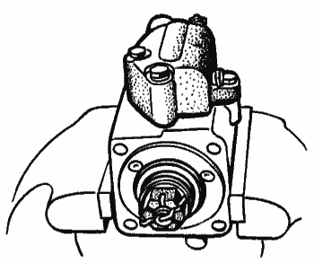
Rice. 2.3.13. Removing the rotary shaft: 1 — power steering housing; 2 - rotary shaft with a sector.
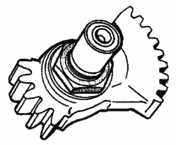
Fig.Fig. 2.3.14. Unscrewing the nut securing the sector to the rotary shaft.
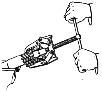
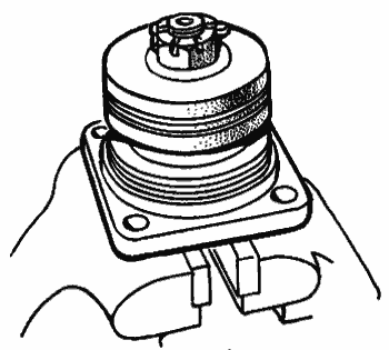
Fig.Fig. 2.3.15. Pressing the sector from the rotary shaft.
Rice. 2.3.16. Removing the differential lock sensor.
Rice. 2.3.17. Removing the differential lock sensor cover.
Rice. 2.3.18. Removing the retaining ring and rack.
Rice. 2.3.19. Removing the power steering cylinder.
Rice. 2.3.20. Unscrewing the fastening nut and removing the piston.
Rice. 2.3.21. Removing the distributor.
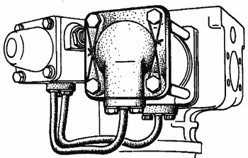
Rice. 2.3.22. Removing the safety valve and worm assembly.
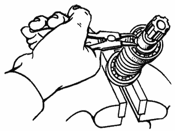
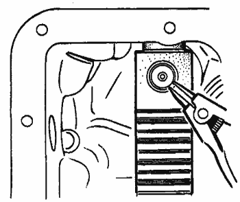
Rice. 2.3.23. Removing the worm bearing retaining retaining ring.
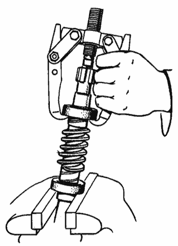
Rice. 2.3.24. Pressing worm bearings.
Rice. 2.3.25. Pressing out the rotary shaft bushing: 1 - bushing; 2 - axle; 3 — puller screw.
Rice. 2.3.26. Tightening the castle nut, worm nut.
The tightening torque is no more than 20 N.m.
When assembling the power steering, special attention is paid to the tightening torques of the nuts, the correct alignment of the marks of the rotary shaft, sector and rack, and the adjustment of the vertical movement of the rotary shaft.
Rice. 2.3.27. Alignment of marks on the end of the rotary shaft spline: 1 - marks; 2 - rotary shaft; 3 - sector.
Rice. 2.3.28. Combination of marks on the middle tooth of the secret shaft and the sector: 1 - marks; 2 - rail; 3 - sector.
Rice. 2.3.29. Tightening the piston nut.
Tightening torque 120N.m.
Rice. 2.3.30. Adjusting the vertical movement of the rotary shaft: 1 - adjusting bolt; 2 - lock nut.
Screw the bolt until it touches the rotary shaft, and then unscrew it 30 - 45° and secure it with a locknut.
Disassembly, assembly and adjustment operations performed during the repair of power steering are quite complex and require the use of control and testing equipment after completion of assembly. The assembled power steering is tested on the control and testing stand KI-4896M. During the tests, the free play of the steering wheel is checked with the vertical power steering shaft fixed, which should be within 4 - 6°, as well as the operation of the hydraulic booster under load at an input pressure of 5 - 6 MPa. The force on the steering wheel rim should not exceed 50N.
Repair of the steering control of the MTZ 80 tractor
Large play in the steering wheel when the engine is running means that there is wear on the steering shaft connections, and there may be increased gaps in the meshing of the power steering gear, ball pins and steering rods. The worm bearings on the shaft may have become loose.
To correct this situation, at the first stage, the technical condition of the steering mechanism parts and steering rods is checked. It is necessary to eliminate the gaps, change the necessary parts and adjust the mechanism.
To find out what the size of the gaps is in the gear and worm gears of the steering mechanism, as well as to determine the force on the steering rim, the NIIAT-402 device is usually used (see Fig. 2.3.1).
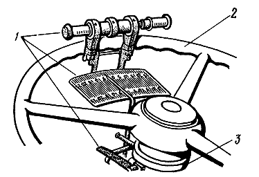
Rice. 2.3.1. How to determine the free play of the steering wheel of the MTZ-80, MTZ-82 tractor: 1 - NIIAT-402 device; 2 steering wheel; 3 - steering column
The dynamometer of the device is placed on the steering wheel, and the pointer is placed on the steering column. By turning the steering wheel in both directions until there are no gaps in the tie rod joints and in the engagement of the steering mechanism, the free play of the steering wheel is calculated. Typical free play of the steering wheel is in the range of 25-30°, and acceptable (permissible) is 35°.
To determine how much force develops on the steering wheel rim, tilt the steering rods away from the bipod, turn on the engine and, at maximum crankshaft speed, pull one of the device’s dynamometer handles. By placing a locking ring on the opposite handle, the force of free rotation of the steering wheel is determined. The steering force should be in the range of 30-50 Newton.
If the steering play is higher than the permissible value, the power steering mechanisms begin to be adjusted. The gaps in the worm-sector gear clutch (see Fig. 2.3.2) are corrected by shifting the adjusting sleeve 4, but first you need to unscrew the locking bolt 3. If the free play of the power steering shaft changes slightly, remove the housing cover (Fig. 2.3.3), and then use a feeler gauge to check the gap between the differential lock sensor (stop) and the rack (Fig. 2.3.4). It should usually be in the range of 0.1-0.3 mm. The gap is adjusted using gaskets for the differential lock sensor flange (Fig. 2.3.5). This procedure is completed by adjusting the worm-sector engagement. What is the deceit? It is necessary that the rotation of the worm is free, without jamming.
|

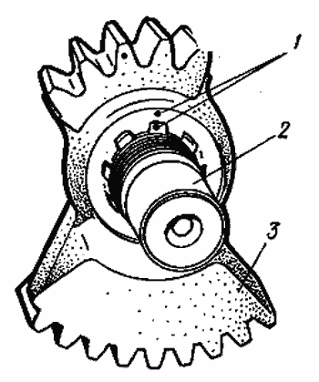
Rice. 2.3.2. How to adjust the gap in the worm-sector engagement by turning the MTZ adjusting sleeve: 1 - dial; 2 — pointer arrow; 3 - lock bolt; 4 — worm adjusting sleeve; 5 - worm
Rice. 2.3.3. How to remove the cover of the power steering housing MTZ-80, MTZ-82: 1 - power steering housing; 2 — power steering housing cover
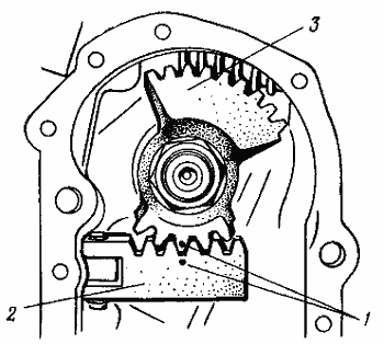
Rice. 2.3.4. How to check the gap between the stop and the rack of the MTZ-80, MTZ-82 tractor: 1 - rack; 2 - dipstick; 3 - stop
Rice. 2.3.5. How to adjust the gap in the worm-sector engagement by installing gaskets MTZ-80, MTZ-82: 1 - power steering housing; 2 — differential lock sensor; 3 - adjusting shims
A heavy turn of the tractor tells us about a lack of working fluid in the tank, a decrease in its supply, or an error in adjusting the safety valve. Another reason is wear or collapse of the power cylinder sealing rings.
The procedure for testing the technical condition of the MTZ rotation control hydraulic system is based on calculating the supply pressure that is developed by the pump. We determine the moments of oil leaks in the distributor and power cylinder and adjust the safety valve. Everything seems to be correct. The required procedures are carried out, as a rule, without removing the steering control hydraulic system units from the tractor, being content with the presence of such a wonderful device as the KI-5473 (throttle-flow meter direction).
The operating modes of the steering control hydraulic system are checked with the device at the rated speed of the engine crankshaft, a back pressure of 5.0 MPa according to the known pressure gauge of the device and a coolant temperature of 50-60 ° C. Next, do not forget that the readings of the device’s flow scale must be multiplied by a factor of 0, 7 L.
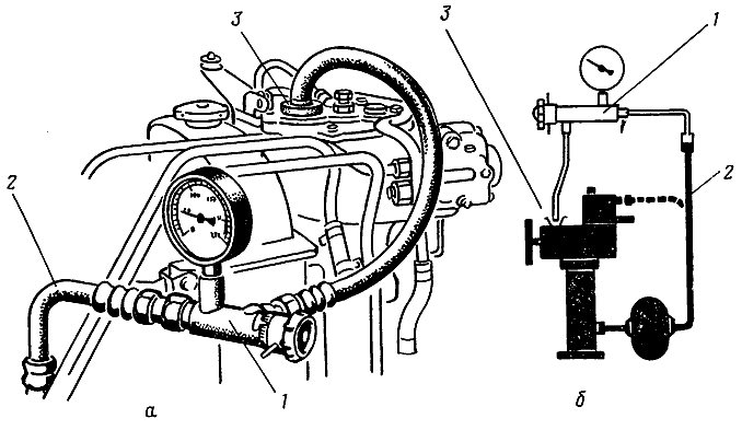
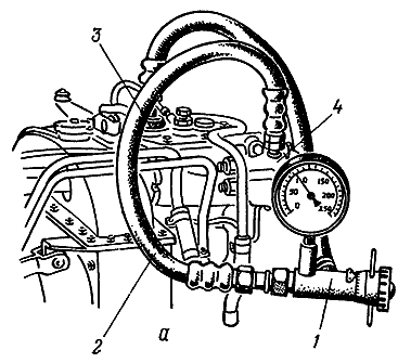
How to check the supply of working fluid to the power steering? According to Figure 2.3.6, discharge pipeline 2 is separated from the safety valve box and the inlet hose KI-5473 is connected to it. The drain hose is placed in neck 3 below the liquid level. Start the engine, adjust the pressure to 5.0 MPa on the pressure gauge at the nominal crankshaft speed, and monitor the supply of working fluid using the instrument scale. If the flow level is low, the pump must be replaced.
If the flow rate is not lower than the permissible value, the condition of the distributor is diagnosed by the amount of oil leakage (Fig. 2.3.7).
|
|
Rice. 2.3.6. How to check the high-pressure power steering pump of the MTZ-80, MTZ-82 tractor: a - connecting the device; b - verification scheme; 1 — device KI-5473; 2 - pump discharge pipeline; 3 - power steering filler neck
Rice. 2.3.7. How to determine an oil leak in the power steering distributor of the MTZ-80, MTZ-82 tractor: a - connecting the device; b - verification scheme; 1 — device KI-5473; 2 — input sleeve of the device; 3 — power steering filler neck; 4 — power steering distributor
Main performance indicators of the power steering distributor when tested with the KI-5473 device
|
| Oil supply at P = 5.0 MPa, l/min: | |
| nominal | 2,0 |
| acceptable | 1,2 |
| Safety valve response pressure, MPa: | |
| nominal | 7,5 |
| acceptable | 7,0-8,5 |
To connect the inlet hose of the device, you first need to unscrew the process plug (it is located on top of the safety valve box). The drain hose is connected to the hydraulic system tank. Start the engine and at the rated crankshaft speed, turn the steering wheel to the right or left until it stops. We rotate the handle of the device and set the pressure on the pressure gauge to 5.0 MPa, and mark the readings on the flow scale. If the difference in instrument readings when monitoring the supply of working fluid to the distributor and checking leaks exceeds 5 l/min, the distributor must be repaired.
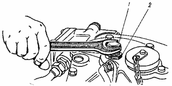
The pressure at which the safety valve of the steering control hydraulic system is activated is determined by a pressure gauge, which is screwed into place of the technological plug (Fig. 2.3.8).
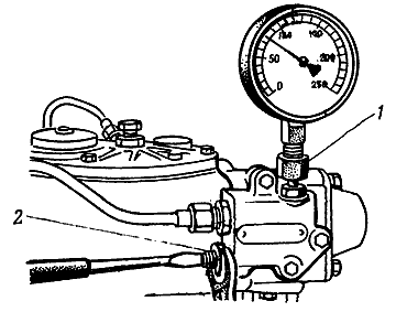
Rice. 2.3.8. How to check and adjust the response pressure of the tractor safety valve: 1 - pressure gauge; 2 - adjusting screw with lock nut
To control, start the tractor engine and at the nominal crankshaft rotation speed, use the handle of the device to completely close the oil drain. The wheels are turned to full. Next, use the pressure gauge to look at the actual pressure at which the safety valve turns on.
The valve must be adjusted in case of low or high response pressure. To do this, unscrew the cap, release the lock nut of the adjusting screw and, holding the steering wheel in the final turning position until it stops, unscrew or screw in the adjusting screw until the required pressure is obtained.
If you find that there are sharp shocks when turning the tractor, then most likely the tightening of the hydraulic distributor spool nut has loosened, or the steering linkage clearances have increased.
If the spool nut becomes loose, the front idler wheels will vibrate. It is clearly felt when moving at high speeds. It should be borne in mind that first you need to adjust the clearances in the steering rod joints, and only then tighten the distributor spool castle nut with a torque wrench to a force of no more than 20 N*m. Then it is released until the holes for the cotter pin are aligned.
What are the main malfunctions of the power steering of the MTZ-80, MTZ-82 tractor? Let's start with the wear of the worm shaft splines and sector teeth. Further wear of the gear rack, wear and leakage of the safety valve. Wear and discrepancy in the hydraulic density of precision parts (spools, plungers, liners).
It is possible that when checking the condition of the units of the hydraulic steering control system of the tractor, faults will be discovered that cannot be eliminated by ordinary adjustment operations. In this case, the power steering is completely removed and disassembled for further technical examination and replacement of parts.
How to do all this, how to competently carry out the basic operations of disassembling, assembling and adjusting the MTZ power steering are demonstrated below in Figures 2.3.9—2.3.30.
Before dismantling the power steering, pour out the working fluid and unscrew the nut of the rotary shaft 4. And already in the process of assembling the hydraulic booster, carefully look at the tightening forces of the nuts, the clarity and unambiguous alignment of the marks of the rotary shaft, sector and rack, and pay attention to the adjustment of the vertical movement of the rotary shaft.
Assembly and disassembly and other adjustment operations that are carried out when repairing a power steering are not entirely simple and require the use of a control and test bench upon completion of assembly to adjust all parameters.
The repaired power steering is brought to perfection using control and testing equipment KI-4896M. During debugging work, check the free play of the steering wheel with the vertical power steering shaft fixed. The range should be between 4-6°. The operation of the hydraulic booster is assessed under load at an inlet pressure of 5-6 MPa. The mechanical stress on the steering wheel rim should not exceed 50 Newton.
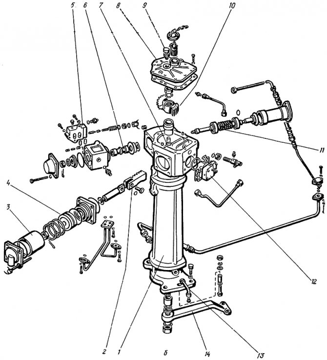
Rice. 2.3.10. What does the power steering (power steering) of the MTZ-80, MTZ-82 tractor consist of: a - general view; b - relative arrangement of parts 1 - amplifier housing; 2 - rail; 3 — power cylinder; 4 - piston; 5 - safety valve; 6 — spool; 7 - rotary shaft; 8 — upper cover of the power steering housing; 9 — adjusting bolt of the rotary shaft; 10 - sector; 11 — worm of the steering mechanism; 12 — differential lock sensor; 13 — drain pipe; 14 — steering bipod
|
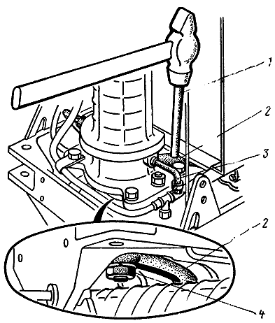
Rice. 2.3.9. Pressing the steering bipod of the MTZ-80, MTZ-82 tractor: 1 - attachment; 2 — steering bipod; 3 - drain pipe; 4 - rotary shaft nut
Rice. 2.3.11. Location of parts of the differential lock sensor of the MTZ-80, MTZ-82 tractor: 1, 10 - bolts; 2 - cover; 3 - spring; 4 - spool; 5 - pusher; 6 - ring; 7, 9 — housings; 8 - valve; 11— tap
Rice. 2.3.12. Removing the oil supply tube from the distributor of the MTZ-80, MTZ-82 tractor: 1 - oil supply tube; 2 — power steering housing; 3 - mesh filter; 4 - pressure reducing valve
Rice. 2.3.13. Removing the rotary shaft of the MTZ-80, MTZ-82 tractor: 1 - power steering housing; 2 - rotary shaft with sector
Rice. 2.3.14. Unscrewing the nut securing the sector to the rotary shaft of the MTZ-80, MTZ-82 tractor
Vis. 2.3.15. Pressing a sector from the rotary shaft of the MTZ-80, MTZ-82 tractor
Rice. 2.3.16. How to remove the differential lock sensor of the MTZ-80, MTZ-82 tractor
Rice. 2.3.17. How to remove the cover of the differential lock sensor of the MTZ-80, MTZ-82 tractor
Rice. 2.3.18. Removing the retaining ring and rack of the MTZ-80, MTZ-82 tractor
Rice. 2.3.19. Removing the power steering hydraulic cylinder of the MTZ-80, MTZ-82 tractor
Rice. 2.3.20. Unscrewing the fastening nut and removing the piston
Rice. 2.3.21. How to remove the distributor of the MTZ-80, MTZ-82 tractor
Rice. 2.3.22. Removing the safety valve and worm assembly of the MTZ-80, MTZ-82 tractor
Rice. 2.3.23. Removing the retaining ring for securing the worm bearing of the MTZ-80, MTZ-82 tractor
Rice. 2.3.24. Pressing worm bearings of tractor MTZ-80, MTZ-82
Rice. 2.3.25. Pressing out the bushing of the rotary shaft of the MTZ-80, MTZ-82 tractor: 1 - bushing; 2 - axle; 3 - puller screw
Rice. 2.3.26. Tightening the worm castle nut
Rice. 2.3.27. Alignment of marks on the end of the rotary shaft spline and the sector: 1 - marks; 2 - rotary shaft; 3 - sector
Rice. 2.3.28. Combination of marks on the middle tooth of the sector and the rack: 1 - marks; 2 - rail; 3 - sector
Rice. 2.3.29. Tightening the piston nut
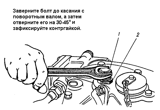
Rice. 2.3.30. Adjusting the vertical movement of the rotary shaft: 1 - adjusting bolt; 2 - lock nut
Large free play of the steering wheel when the diesel engine is running indicates wear on the steering shaft connections, increased clearances in the meshing of the power steering gear, ball pins and steering rods, and weakening of the worm bearings on the shaft.
To eliminate malfunctions of the MTZ-80 steering, check the technical condition of the steering mechanism parts and steering rods, eliminate gaps, replace parts, and adjust the mechanism.
To determine the gaps in the gear and worm gears of the steering mechanism, as well as the force on the rim of the steering wheel, the NIIAT-402 device is used.
The dynamometer of the device is installed on the steering wheel, and the pointer is installed on the steering column. By rotating the steering wheel in both directions until the gaps in the steering rod joints and in the engagement of the steering mechanism are eliminated, the free play of the steering wheel is determined. The nominal free play of the steering wheel corresponds to 25-30°, the permissible free play is 35°.
The design and principle of operation of the MTZ-80 power steering. Adjustments and repairs.
For comfortable and efficient driving, the steering mechanism of the MTZ 80(82) tractor is equipped with power steering. The unit performs the function of transmitting rotation from the steering wheel to the steering bipod while simultaneously easing the effort when turning and mitigating reverse vibration when driving on roads with uneven surfaces. Strengthening is achieved by fluid pressure acting on the working parts of the mechanism.
The unit was installed on earlier MTZ-80(82) models and is not inferior in its functional and performance qualities to the later installed hydrostatic power steering system - GORU.
Adjusting the toe-in of the front wheels of the MTZ-80 and MTZ-82 tractors
Adjusting the toe-in of the front wheels of the MTZ-80 and MTZ-82 tractors
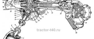
Periodically (every 240 hours of operation of the MTZ-82 tractor and after 960 hours of operation of the MTZ-80 tractor, as well as every time the front wheel track changes), check and, if necessary, adjust the wheel alignment (Fig. 56). Before checking alignment, be sure to check and, if necessary, adjust the clearances in the wheel bearings and steering rod joints as indicated above. To check the convergence, install the tractor for straight-line movement (the wheels and bipod are parallel to the axis of the tractor), the length of the left and right steering rods, determined by the distance between the ball pins C, must be the same, and the bodies of the conical pairs or steering knuckles are extended to the same length B, respectively, from the body and front axle and front axle covers.
Rice. 56. Determination of the toe-in of the front wheels of the MTZ-82 and MTZ-82L tractors:
1 — rotary lever; 2 — tie rod end; 3 - lock nut; 4 — steering rod pipe; 5 — control plug; 6 — steering rod joint; 7 — filler plug; 8 - lock nut.
To determine wheel toe-in, measure the distance between the inner edges of the rims in front (at the height of the wheel centers) and mark with chalk the places where measurements were taken. Then move the tractor forward so that the marks are behind at the same height, and measure the distance between the marked points.
The second measurement should be greater than the first, the difference between the second B and first A measurements is equal to the wheel toe-in value and should be within 4-8 mm.
To adjust the toe-in of the wheels, release locknuts 16 and 17 (Fig. 51) or 3 and 5 (Fig. 56) from the steering rods and, by rotating the left and right pipes of the rods, shorten or lengthen them by the same amount. Then the difference between sizes B and A is checked again.
After adjustment, the pipes must be securely locked with locknuts.
It should be remembered that incorrectly set wheel alignment causes emergency tire wear.
traktor-mtz82.ru
Design and principle of operation
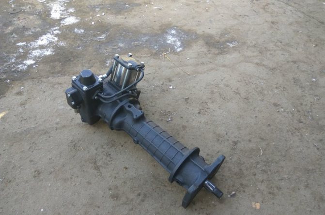
The cast iron housing of the MTZ 80 (82) power steering is located on the front frame beam between the front front wall of the hood and the diesel engine cooling radiator of the machine. The unit is a mechanism with a worm gearbox, equipped with an autonomous hydraulic system with a spool for controlling the flow of working fluid, a left-hand rotation gear hydraulic pump NSh-10-L-U GOST 8753-71, a double-acting power cylinder and a safety valve. The system's hydraulic pump is driven by the engine timing gear.
A worm is installed in the amplifier body, connected by turns to the sector and its end part to the valve spool of the assembly. At the ends of the spool there are thrust bearings, into which the plungers rest under the pressure of the springs. At the same time, the outer sides of the plungers rest against the housing parts of the distributor. Plungers and springs hold the spool in the neutral position through bearings. When the steering wheel rotates, the worm begins to move the sector in turns, turning the bipod shaft. The resulting resistance of the wheels is transmitted through the mechanism to the worm, forming a force that moves it axially forward or backward depending on the direction of rotation. By its displacement, the worm interacts with the valve spool of the assembly, moving it relative to the axis. Thus, the spool controls the flow of oil under pressure. When moving straight, the distributor spool, spring-loaded, is in the neutral position, the pressure supplied by the pump is released into the amplifier housing, which is the hydraulic tank of the system.
By rotating the steering wheel, the worm moves the spool, which opens the lines of the cavities of the power cylinder with its belts. Moreover, depending on the direction of rotation, one cavity is connected to a line supplying oil under pressure, the other to a drain. The spool drops pressure into the cylinder cavity only during direct rotation of the steering wheel. When the steering wheel stops, the worm stops acting on the distributor spool, which, under the force of the springs, takes a neutral position, dumping oil into the drain cavity.
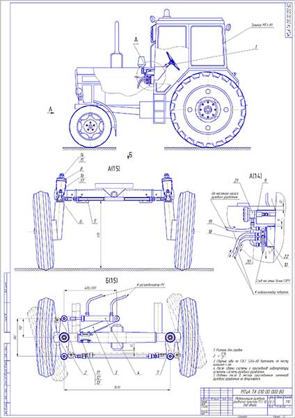
Diploma Modernization of the steering control of the MTZ-80 tractor
The goal of the diploma project is to reduce the costs and labor intensity of maintenance and repair of the steering control of MTZ-80 tractors.
When completing the diploma project, an analysis of the steering control structures of MTZ-80, 82 tractors and grain harvesters was carried out, and the advantages and disadvantages of their steering systems were considered. A rational steering scheme for the MTZ-80 tractor was selected, which ensures a reduction in the steering wheel play by reducing the mechanical connections in the steering mechanism. To reduce the labor intensity and costs of maintenance and repair, the design uses hydrostatic steering similar to those used in the design of grain harvesters. The calculation of the hydraulic system of the modernized steering and the kinematic calculation of the turning mechanism were carried out.
The project examines labor protection and environmental issues during operation, repair and maintenance of the MTZ-80 tractor with modernized steering. The economic efficiency of using a modernized steering design has been calculated.
1. As a result of the analysis of the design of the steering control of the MTZ-80 tractor and the SK-5 “Niva” and “Kolos” combine harvesters, it was established that the hydrostatic steering control of grain harvesters has design and operational advantages over the mechanical one, while the weight of the structure is 2.5 less -3 times.
2. Hydrostatic steering of grain harvesters, correctly assembled and adjusted, filled with clean oil of the required quality, is highly reliable, durable and does not require maintenance for many years of operation. In this regard, its use in the design of MTZ-80 tractors is quite effective.
3. A rational steering control scheme for the MTZ-80 tractor, developed on the basis of the hydrostatic steering control of grain harvesters, is proposed.
4. As a result of modernization of the steering control of the MTZ-80 tractor, the following is provided:
- reducing the weight of the steering structure by 2 times;
- reducing the clearance in the tractor steering to 4-6 degrees. instead of 28 degrees. in the basic version, which makes it easier to control the tractor;
- reducing the labor intensity of tractor steering maintenance by 6-7 times.
5. The hydraulic system of the modernized steering control of the MTZ-80 tractor and the kinematic calculation of the turning mechanism were calculated.
6. Safety rules for working on the MTZ-80 tractor with a modernized steering system are proposed, environmentally hazardous elements of the modernized design are identified and environmental requirements are given.
7. As a result of calculating economic efficiency, it was determined that the use of modernized steering on the MTZ-80 tractor provides an annual economic effect of 22.8 thousand tenge per tractor. The payback period for modernization is 2.6 years.
Modernization of the steering control of the MTZ-80 tractor
Detailed modernization of the steering control of the MTZ-80 tractor
Content
Introduction 8
1. General characteristics and analysis of the use of MTZ-80 tractors in production 9
- 1.1 General characteristics of MTZ-80 tractors
- 1.2 Analysis of the operation of MTZ-80 tractors in agricultural production conditions
2. Analysis of steering structures of tractors and combine harvesters 15
- 2.1 Purpose and types of steering
- 2.2 Design of the steering control of the MTZ-80 tractor
- 2.3 Steering design of combine harvesters
- 2.4 Chapter Conclusions
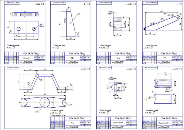
3. Structural part 33
- 3.1 Description of the proposed design of the steering control of the MTZ-80 tractor
- 3.2 Calculation of the hydraulic system of the modernized steering
- 3.2.1 Distributor calculation
- 3.2.2 Calculation of power hydraulic cylinder
- 3.2.3 Calculation of hydraulic fittings
- 3.3 Calculation of the bolted connection of the hydraulic cylinder bracket
- 3.4 Kinematic calculation of the modernized steering drive
- 3.5 Calculation of steering linkage threads for shear and crushing
- 3.6 Test calculation of the hydraulic cylinder bracket for strength
4. Labor protection 48
- 4.1 Analysis of the safety of work when operating the MTZ-80 tractor with modernized steering
- 4.2 Safety requirements for operation and maintenance of the MTZ-80 tractor
- 4.2.1 General technical safety requirements
- 4.2.2 Industrial hygiene requirements
- 4.2.3 Fire safety requirements
- 4.2.4 Electrical safety requirements
- 4.2.5 Ergonomic requirements
- 4.3 Safety requirements for operating the MTZ-80 tractor with modernized steering
5. Environmental protection 54
6. Feasibility study for modernizing the steering control of the MTZ-80 tractor 57
Conclusion 61
List of references 62
Tags: Diploma Modernization of the steering control of the MTZ-80 tractor
Adjustments
The node is configured in good condition. Its correctness is an important factor in the efficient operation of the amplifier and preservation of its service life. The adjustment is divided into adjusting the gearing gaps of mechanical pairs and the spool stroke.
Worm-sector engagement
The adjustment is made when the steering rods and steering joints are in good condition; the free play of the steering wheel should not exceed 30 ̊ with the engine running.
- The front axle of the tractor is jacked up or the bipod is disconnected from the steering rods.
- Loosen the bolt of the adjusting eccentric sleeve.
- Turn the bushing clockwise until the worm stops in maximum engagement with the sector.
- With the engine running, turn the steering wheel to determine the engagement position without feeling stuck, increasing the gap by turning the bushing counterclockwise.
- Tighten the bushing mounting bolt, remove the bridge from the jack or connect the bipod to the steering rods.
Tightening the worm spherical nut
Tightening the nut eliminates the gap between the spool and the bearing races, formed as a result of wear or weakening. The appearance of a gap is reflected in an increase in the free play of the steering wheel and the appearance of the effect of dangling steering wheels. When play appears, the spool can arbitrarily connect the cylinder cavities to the oil pressure lines.
- Unscrew the bolts securing the distributor to the amplifier body.
- Remove the cover and attach the distributor to two diagonally placed bolts 5 . The thickness of the cover flange is compensated by backing washers 4 or large diameter nuts under the bolt heads.
- Then unscrew the adjusting nut 1 and tighten it until the spool stops in the bearing races. Tightening is carried out with a force of 20 Nm.
- By unscrewing the spherical nut until the hole on the worm shaft first matches, the nut is secured with a cotter pin.
- Dismantle the installation bolts with washers and install the cover with the gasket, tightening with four bolts as usual.
Correct tightening ensures that the spool fits snugly against the bearing races and ensures that the spool returns to the neutral position under the action of the springs when the steering wheel stops rotating. Excessive tightening increases the force on the steering wheel and leads to rapid wear of the distributor thrust bearings.
Adjusting the sector-rack engagement
The gap in the sector-rack engagement of the cylinder piston rod is regulated by the number of spacers between the amplifier body and the rack stop. A sufficient gap of 0.25-0.3 mm ensures the pair operates without jamming.
Spool stroke uniformity
The spool stroke is controlled by shims between the amplifier body and the distributor, the distributor and the spherical nut cover. If the rotation to the left is insufficient, an additional gasket of 0.5-1 mm is installed between the column body and the distributor; if the rotation to the right is insufficient, a gasket is installed under the spherical nut cover. Thus, the amplitude of the spool stroke from left to right is equalized.
System pressure
The pressure of safety valve 7 is adjusted by changing the spring compression. By tightening the valve screw, the compression of the spring increases and, accordingly, the maximum operating pressure of the amplifier hydraulic system.
Malfunctions and repairs
The first criterion affecting the efficiency of the unit is the tightness of all seals of the hydraulic system, which maintain the working pressure of the fluid, providing force on the working parts. Elimination of oil leaks and pressure loss is achieved by replacing all rubber seals, O-rings and gaskets included in the complete power steering repair kit.
The serviceability of the joints of the mechanical drive, the adjustment of the engagements of the worm gearbox and the piston rack with the sector ensure the operation of the mechanism without jamming.
The reason for a tight steering wheel, if the system is well sealed and the oil level is sufficient, may be poor compression of the power piston of the amplifier cylinder or insufficient stroke of the distributor spool, which does not allow opening the discharge line to the cylinder cavities.
Replacing the compression rings on the piston and the sealing ring on the rod eliminates the flow of oil from the injection cavity into the drain, increasing the efficiency of the cylinder and, accordingly, the generated useful force.
With proper adjustment and in good condition, for the spool to fully open the channels, the working stroke in one direction should be 1.2 mm. If the stroke is disrupted, the distributor does not perform its function, which leads to incomplete opening of the discharge channel to supply pressure to the cylinder cavity and sufficient hydraulic gain is not created. Often the cause is unacceptable play in the connections of the amplifier assembly units, which in their total negatively affect the provision of the required parameters for the movement of the spool. Therefore, it must be said that the success of the distributor depends on the technical condition of the connections of the parts and the compliance of the gaps in the gears.
It is technically sound and correct to replace the failed parts in case of unacceptable backlash or impossibility of adjustment as a result of wear of the contact working surfaces of teeth, worm turns, bushings, and bearings.
Many tractor drivers use in practice a technique that temporarily levels the gaps when power steering parts wear out and affect the operation of the distributor. The normal working stroke of the spool is achieved in two ways:
- The linear size of the spool is increased by grooving on both sides of the internal diameter of the part with a width of 4 mm and a body depth of 1 mm. Sleeve-washers are machined with the appropriate width and diameter to fit into the inner diameter of the spool recess and the protruding part with a width of 1.2 -1.5 mm with the corresponding outer diameter. The upgraded part is installed by placing additional gaskets between the column body and the distributor and the distributor cap. In this way, the increased size of the spool is compensated. To increase the rigidity of the plunger springs, additional washers of the appropriate diameter with a thickness of 1.5 mm are machined and installed between the spring and the part.
- The second method is simpler - grind the cover mounting surface on the distributor body. The diameter of the groove from the center of the hole for installing the spool and the worm axis is made 4 mm larger than the diameter of the thrust bearing race with a depth of 2-2.4 mm. In this case, there is no need to install additional gaskets between the bodies and covers, as well as install washers under the plungers.
The described technique takes place in practice, however, it does not solve the problem of the general technical condition of the unit. Increased gaps in the joints as a result of wear or improper adjustment will still lead to a complete failure of the unit to perform its function. Therefore, before resorting to this method, try to determine the cause of insufficient spool travel and eliminate it by replacing worn parts with subsequent adjustment, according to the manufacturer’s operating recommendations.
Purpose of power steering
Before studying in more detail the structure of the MTZ 80 steering column, as well as possible malfunctions of this important unit, it is advisable to become more familiar with its purpose and features. Power steering of MTZ tractor equipment is designed to reduce the driver’s efforts required to perform maneuvers when driving a vehicle.
If you study the design of the tractor, you can conclude that this unit appears to be intermediate between the steering wheel and the wheels of the tractor. All steering components, as well as hydraulic elements, are installed under the radiator.
List of nodes
When planning to figure out how to repair the MTZ 80 steering column with your own hands, you should study the design of this component. The power steering is equipped with a separate hydraulic system, which does not depend on similar elements that are part of the internal structure of the tractor.
The main elements of the steering hydraulic system are a distributor, metering and cylinder pumping devices, as well as a sensor for automatically locking the rear axle of the vehicle. Considering the design of the hydraulic booster in more detail, it is necessary to mention the following important elements:
- the housing where the oil tank is located serves for mounting most of the power steering parts and elements;
- a pump that makes it possible to move oil in the hydraulic system;
- the sector in contact with the steering is located on the rotary shaft;
- rotary shaft equipped with 3 support elements;
- a rack that transmits the movement of the piston to the sector;
- a spool mounted on one of the ends of the worm gear of the steering column;
- a filter used to clean the oil circulating in the hydraulic system;
- a safety valve, the main purpose of which is to protect the unit from excessive pressure.
If you want to know how to troubleshoot the steering column, you need to pay attention to another important design element - the automatic locking system. It is designed to lock the rear axle differential and includes several components.
Possible faults
The products of the Minsk Tractor Plant are of high quality, excellent technical characteristics and long service life, but over time they may require repairs and adjustments. Owners of MTZ tractors have to deal with several typical power steering breakdowns, which include:
- tight steering;
- the tractor does not turn in the right direction;
- There are delays in the operation of the node.
To eliminate such faults, it is strongly recommended to disassemble the unit and troubleshoot individual elements, and then replace the damaged parts with new ones. After carrying out the work, you will need to install the unit in place, and then adjust it.
Setup and repair
If it is necessary to improve the power steering MTZ 80 or eliminate minor damage, it is enough to perform a detailed adjustment of this mechanism. To do this, it is advisable to adhere to the following instructions:
- Loosen the main bolt located at the worm-sector engagement point.
- Using a wrench, turn the bushing clockwise until it stops, then turn it in the opposite direction by 1-1.2 cm.
- Tighten the main bolt, start the engine and make sure the steering wheel rotates correctly.
- If binding is detected, you will need to increase the engagement gap by turning the bushing counterclockwise.
- Adjust the sector-rail connection by reducing the thickness of the adjusting shims until they stop. The extreme position can be determined by the gap between the rail and the stop, which will reach 0.1-0.3 mm.
- Tighten the thrust bearings using a ball nut, being careful not to over-tighten them.
In addition to adjusting the unit, maintenance may need to be performed to help keep the power steering in optimal condition. Most often, it is necessary to wash the oil filter, which can be done by lifting the lining, dismantling the oil line and cover.
Some breakdowns, such as difficulty turning, may indicate insufficient fluid volume in the hydraulic system, improper adjustment, or worn cylinder o-rings.
Measures to repair hydraulic steering mechanisms of a tractor seem to be quite complex and require special equipment to monitor performance indicators. In some cases, it may be easier to install the MTZ 80 power steering assembly, which will avoid problems with finding broken elements. To do this you will need:
- Make sure the oil supply system is tight.
- Install the assembled mechanism on special bushings located on the front beam of the semi-frame.
- Mount the steering shaft into the column, as well as install other elements.
Purchasing an assembled hydraulic booster seems to be a much more expensive solution than sequential adjustment and troubleshooting of its parts, but it allows you to quickly solve problems that have arisen.
Functions of the MTZ 80 gyro amplifier
The device of modern technology allows:
- Increase the maneuverability of the machine even in difficult areas;
- Quickly and reliably link the tractor wheel guides into a single system.
The MTZ 80 hydraulic booster device includes many elements.
The distribution unit, hydraulic tank, blocking sensor, MTZ power steering are located in a single housing.
The unit is mounted directly in front of the surface of the tractor radiator.
Thanks to the reliable protection of the MTZ cladding, the MTZ hydraulic booster can withstand heavy loads.
Let's take a closer look at the MTZ 80 power steering device:
- Differential lock sensor;
- Tank for filling with working fluid;
- A gear pump is installed to the left of the motor;
- Safety valve;
- Power cylinder.
All parts of the MTZ 80 power steering are equipped with a strong housing.
Thanks to the use of durable materials, components last a long time.
Let us remind you that you can buy everything for replacing, installing and repairing MTZ power steering in the catalog.