MTZ tractor engines are equipped with a removable head, which is installed on the cylinder block and secured with bolts. The reliability of the power unit depends on the correct installation of parts and compliance with the tightening torque of the MTZ cylinder head. When exhaust gases or coolant break through, power is reduced and components of the piston group and gas distribution mechanism of the engine are destroyed.
The importance of correct cylinder head torque
The cylinder head is held on the crankcase with bolts that evenly distribute the compression force of the parts, preventing the destruction of the gasket by hot gases. To ensure uniform contact, the bolt is tightened with a torque wrench; the threaded connections are tightened according to the pattern laid down by the developer of the power unit. The gasket installed between the head and the block is deformed when tightened, ensuring the tightness of the joint line.
If the tightening torque is exceeded, deformation of the bolt and thread cut in the body of the block occurs. Due to the stretching of the rod of the connecting part, the uniformity of the mating planes of the head and the block is disrupted, which leads to breakdown of the gasket by the gas flow. A similar problem occurs if the cylinder head to block bolts are not tightened enough.
GAS DISTRIBUTION MECHANISM OF DIESEL D-245 OF MTZ-100, MTZ-102 TRACTORS
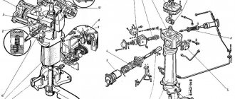
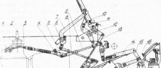
The valve timing mechanism is designed to admit air into the cylinder and release exhaust gases from it at certain points in time. The mechanism consists of a camshaft 1 (Fig. 7), gears 2, 3, 4 and 6 (Fig. 8), pushers 2, rods 5, axles 8 with springs 12 and 13, plates 9 and crackers 10. The valves are actuated from the camshaft through pushers, rods, adjusting screws b and rocker arms 7, overcoming the force of springs 12 and 13.
The camshaft is three-bearing, driven by the crankshaft through distribution gears b, 3 and 2 (see Fig. 8). Sliding bearings are used as camshaft supports, which are made in the form of bushings pressed into the block bores. The camshaft cams are made with a slight inclination to the shaft axis. Changing the point of contact between the cam and the follower ensures uniform and less wear.
Rocker arms 7 (see Fig. 7) of the valves are freely mounted on a hollow axis 8, which is mounted on racks II attached to the top
plane of the head of 15 (see Fig. 4) cylinders. Lubricant is supplied to the rocker arms through the radial holes in the axles.
Intake and exhaust valves 4
(see Fig. 7) move in guide bushings 3, pressed into the cylinder head. The valves close under the action of the outer 13 and inner 12 springs, which with their lower ends rest on the cylinder head, and with their upper ends on plate 9, held on the valve stem by nuts 10. The distribution gears (see figure) are located in the crankcase, which is formed by a distribution board attached to the block of 17 cylinders (see Fig. 4), and a cover of 5 timing gears.
The quality of filling and emptying of the cylinders depends on the duration of opening and closing of the valves.
The intake valve opens with some advance, i.e., before the piston reaches top dead center (TDC), and closes with some delay, i.e., after the piston passes the bottom dead center (B.M. .T.). This allows the intake duration to be increased.
The exhaust valve opens before the piston reaches the b.m.t., and closes after passing the b.m.t.
Rice. 7. Diesel D-245 (cross section): 1 - camshaft; 2 - pusher; 3 — valve guide; 4 ~ valve; 5 — rod; 6 — adjusting screw; 7 — rocker arm; 8 — rocker axis; 9 - plate; 10 - cracker; 11 - stand; 12 — internal spring; 13 - outer spring.
Rice. 8. Diagram of installation of timing gears: 1 - hydraulic pump drive gear; 2 - camshaft gear; 3 - intermediate gear; 4 — fuel pump drive gear; 5 - oil pump drive gear: 6 - crankshaft gear.
content .. 1 2 3 9 ..
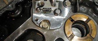
Preparing the tightening surface of the block and head
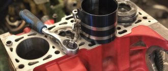
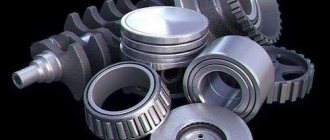
The head is installed in its original place after partial or major repair of the engine units and components. Before installing the head, new liners are installed in the block, which are sealed with special rubber rings that prevent coolant from leaking out of the jacket. The installed sleeve protrudes with its upper edge above the plane of the block. Pistons and liners are selected according to one size group, and the connecting rods and pistons are additionally weighed. The permissible difference in weight should not exceed 30 g.
To connect the connecting rod and piston, the pin is pressed into the piston using a special mandrel, and then secured against longitudinal movement with locking rings. A correctly selected finger does not move in the mounting sockets under the influence of its own weight.
The skew of the pin in the hole of the connecting rod bearing, as well as bending or conical wear of the cylindrical element is not allowed.
Rings are installed in the grooves on the piston body to provide compression and remove traces of oil from the surface of the liner. MTZ naturally aspirated engines use 3 compression rings, supercharged engines are equipped with 2 rings, the top one is coated with a wear-resistant chromium-based alloy. The ring locks are placed at 180° intervals, providing increased compression. When installing parts, you need to pay attention to the marks indicating the correct location of the rings relative to the piston bottom.
Before installing the pistons, it is necessary to install the crankshaft in its original place (if it was dismantled for grinding from the replacement). Then a piston with a connecting rod is installed in the cylinder liner, after which the liners are mounted and the caps of the main and connecting rod bearings are tightened. To check the correct assembly, use a torque wrench to turn the engine shaft.
The standard force should not exceed 60 N/m; if there is increased resistance to rotation, it is necessary to find the cause of the malfunction.
Installing the gasket and cylinder head on the block
The gasket is placed on the upper surface of the block, previously wiped with a clean rag. It is first recommended to check the condition of the aligned planes of the block and head with a metal tool ruler. Warping of parts is not allowed, since curved surfaces do not provide uniform clamping of the gasket, which will be pierced by the flow of exhaust gases. Damaged planes are ground on a special machine, and a metallized gasket with an increased thickness of material is used to seal the joint.
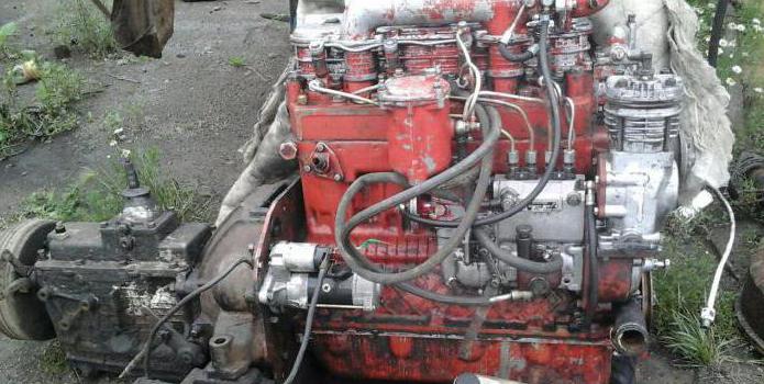
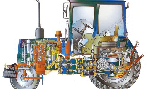
Engine D-245
In order to ensure a better level of acceleration, a turbine compressor is used with the ability to adjust the air flow. This ensures an increased level of torque even at a minimum number of crankshaft revolutions. At the same time, such an engine with a turbine exhausts exhaust gases that comply with European standards Euro 3. But the entire series of such engines is intended for use only in ambient temperatures ranging from -45 to +45 degrees. The main place of use of these units is their installation in road, construction, and wheeled equipment.
Timing belt and valves of diesel D-245
Timing distribution mechanism D-245 for ZIL-5301 Bychok, GAZ-3309, MAZ-4370 gear The gear consists of a camshaft, intake and exhaust valves, as well as parts for their installation and drive: pushers, rods, rocker arms, adjusting screws with nuts, plates with crackers, springs, struts and rocker axles.
The camshaft is a five-bearing one, driven by the crankshaft through distribution gears. The camshaft bearings are five bushings pressed into the block bores.
The front bushing (from the fan side) is made of aluminum alloy and has a thrust collar that holds the D-245 camshaft from axial movement; the remaining bushings are made of special cast iron.
Valve pushers are steel. The working surface of the pusher plate is overlaid with bleached cast iron and has a spherical surface of large radius (750 mm). As a result of the fact that the camshaft cams are made with a slight inclination, the tappets perform a rotational movement during operation.
The push rods are made of steel rod. The spherical part that goes inside the pusher and the rod cup are hardened. The valve rocker arms are made of steel and swing on an axis mounted on four racks. The outer pillars are of increased rigidity.
The rocker arm axis is hollow and has eight radial holes for supplying oil to the rocker arms. The movement of the rocker arms along the axis is limited by spacer springs.
Inlet and exhaust valves D-245 are made of heat-resistant steel. They move in guide bushings pressed into the cylinder head. Each valve closes under the action of two springs: external and internal, which act on the valve through a plate and crackers.
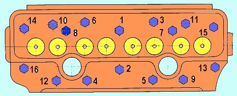
Cylinder head tightening order and tightening force
The mounting bolts are tightened with a torque tool in accordance with the diagram given in the technical documentation. The algorithm for tightening the head bolts is identical for naturally aspirated engines and units equipped with supercharging. The fasteners are first tightened with a force of 70-90 N/m, and then the second stage of fixation is carried out with a torque of 170-190 N/m (step-by-step tightening is used only for the diesel version with a turbocharger). Between steps there is a pause of 5-6 minutes, necessary for uniform deformation of the gasket.
The final fixation of the parts is carried out with a force of 190-210 N/m (atmospheric model) or 230-250 N/m (supercharged version); applying more force is strictly prohibited.
If at least 1 fastening element rotates in the body of the block or the rod breaks (or the head breaks), then you will need to dismantle the head and restore the thread. Operation of the motor with a damaged head mounting element is not allowed.
AUTOFIZIK.RU / auto repair
The sequence of adjusting valve clearances when installing the piston of the first cylinder to the TDC position
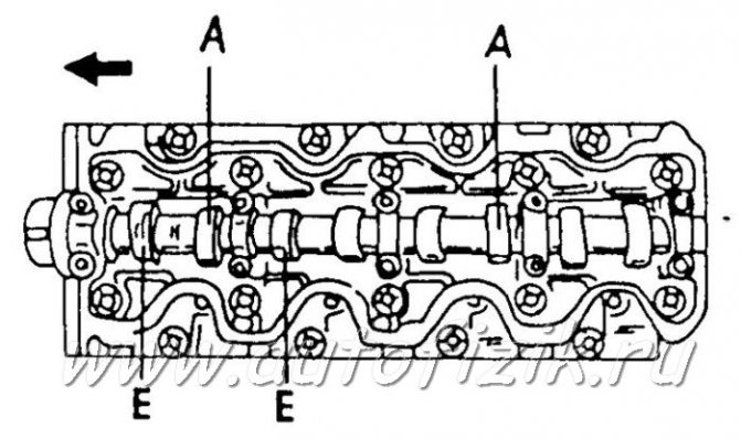
E – intake camshaft A – exhaust camshaft Sequence of valve clearance adjustment when setting the piston of the fourth cylinder to the TDC position
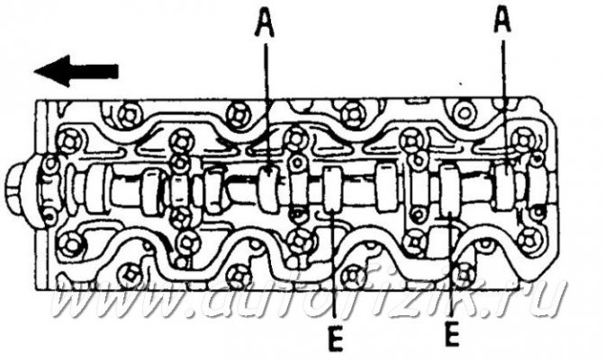
E – intake camshaft A – exhaust camshaft Using a special tool to press the tappets into their holes
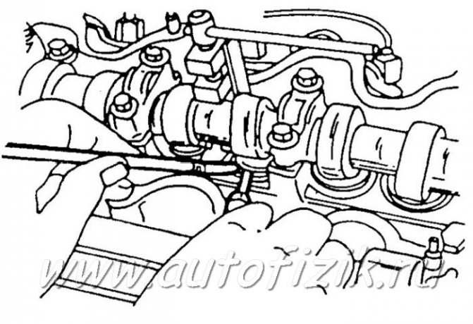
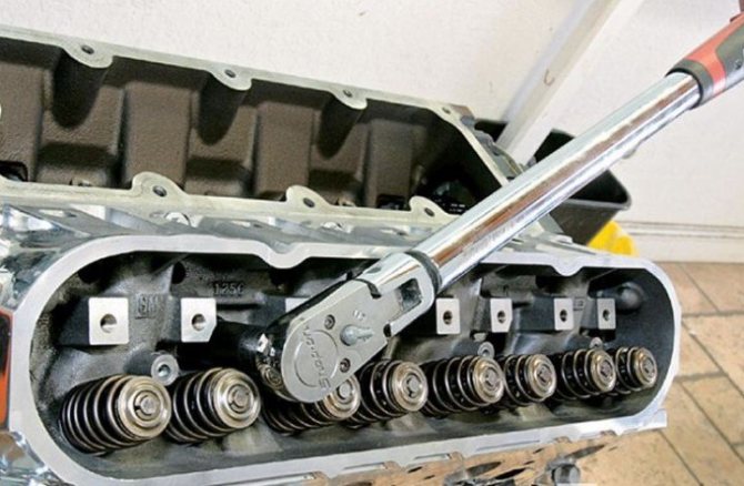
A screwdriver and a magnet are used to remove the adjusting washers. On diesel engines, valve clearances are checked and adjusted when the engine is cold. PERFORMANCE ORDER 1. Remove the cylinder head cover. 2. Crank the engine until the piston of the first cylinder is in the TDC position. In this case, the mark on the pulley should coincide with the pin on the oil pump housing. 3. Check that the valve lifters of the first cylinder have a slight play, and the valve lifters of the fourth cylinder are seated tightly. If not, turn the engine one more revolution. 4. Measure according to the pic. The sequence of adjusting the valve clearances when setting the piston of the first cylinder to the TDC position using feeler gauges inserted between the pusher and the cam surface, valve clearances. The clearances of the intake (E) and exhaust (A) valves are not the same on all engines and are given in the size and adjustment tables. 5. Turn the engine one full turn and measure the gaps shown in Fig. The sequence of adjusting the valve clearances when installing the piston of the fourth cylinder to the TDC position. A sign of proper adjustment is when the end of the feeler gauge is inserted and then, with light pressure, the feeler gauge bends and goes in. 6. To adjust the valve clearances, the shims on the top side of the pushrods must be replaced, but a special tool is required to remove and install the shims. To do this, rotate the crankshaft until the corresponding cam is installed with the tip up and using the special tool shown in Fig. Using a special tool to press the pushrods into their holes, or otherwise press the pushrod inward so that you can grab and pull out the shim with a small screwdriver and a magnet. 7. Before pressing the pusher, it should be turned so that the notch on the top side faces the spark plugs. Both pushers are pressed simultaneously, that is, it is necessary to ensure that both pushers are pressed by the foot of the device. 8. Measure the removed washer with a micrometer and record the result. 9. Calculate the thickness of the new washer to provide the required valve clearance. The following formula is used: Intake valves: N = T + (A – 0.25 mm); Exhaust valves: N = T + (A – 0.30 mm), where “T” is the thickness of the removed washer. “A” is the measured valve clearance and “N” is the thickness of the new washer to be installed. 10. Select a washer that is closest in thickness to the required clearance. There is a range of 25 sizes of washers ranging in thickness from 2.2mm to 3.4mm at 0.05mm intervals. 11. To install the shim, press the pusher inward again and insert the washer. 12. Measure the valve clearance as described above. 13. Adjust the clearances of the remaining valves. Warning The adjusting washer must not fall into the engine under any circumstances. To avoid this, use a small screwdriver and a magnet, as shown in Fig. Using a special tool to press the pushrods into their holes. The washer can then be pulled to the side and “grabbed” by the magnet.
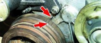
Tightening the cylinder head bolts of the D-240 engine
The tightening of the cylinder head bolts should be checked after 40 t km and in those cases after installing the cylinder head during engine repairs, and after a couple of days of operation, to allow for shrinkage of the cylinder head gasket. If this is not done, then the cylinder head gasket may burn out and coolant may still leak into the engine sump.
We tighten the bolts on a warm engine, approximately 60 degrees in the following order.
Tightening the cylinder head bolts
- Unscrew the top valve cover.
- We unscrew the rocker arm axle (don’t forget about the oil supply).
- Check the tightness of all cylinder head bolts with a torque wrench in a specific sequence, as shown in the figure. The tightening torque with a wrench is 220-10 Nm. After tightening the cylinder head bolts, reinstall the rocker arm axle and tighten the struts. Next, adjust the valve clearances.
Torque wrench
You can adjust the valves yourself. It is necessary to adjust the valves on the engine in some cases. This is done after each removal of the cylinder head, after 480 hours of engine operation, after pulling the cylinder head, when knocking valves, after running in a new engine, and timely engine maintenance.
Adjustment of the MTZ engine valves must be done on a warm engine at 60-40 degrees. Before making adjustments, be sure to tighten the rocker shaft mounts. The operation of your engine, its durability, and fuel consumption depend on proper valve adjustment.
Timing belt and valves of diesel D-245
___________________________________________________________________________
Timing belt and valves of diesel D-245
Timing distribution mechanism D-245 for ZIL-5301 Bychok, GAZ-3309, MAZ-4370 gear The gear consists of a camshaft, intake and exhaust valves, as well as parts for their installation and drive: pushers, rods, rocker arms, adjusting screws with nuts, plates with crackers, springs, struts and rocker axles.
The camshaft is a five-bearing one, driven by the crankshaft through distribution gears. The camshaft bearings are five bushings pressed into the block bores.
The front bushing (from the fan side) is made of aluminum alloy and has a thrust collar that holds the D-245 camshaft from axial movement; the remaining bushings are made of special cast iron.
Valve pushers are steel. The working surface of the pusher plate is overlaid with bleached cast iron and has a spherical surface of large radius (750 mm). As a result of the fact that the camshaft cams are made with a slight inclination, the tappets perform a rotational movement during operation.
The push rods are made of steel rod. The spherical part that goes inside the pusher and the rod cup are hardened. The valve rocker arms are made of steel and swing on an axis mounted on four racks. The outer pillars are of increased rigidity.
The rocker arm axis is hollow and has eight radial holes for supplying oil to the rocker arms. The movement of the rocker arms along the axis is limited by spacer springs.
Inlet and exhaust valves D-245 are made of heat-resistant steel. They move in guide bushings pressed into the cylinder head. Each valve closes under the action of two springs: external and internal, which act on the valve through a plate and crackers.
Sealing collars installed on the valve guides prevent oil from entering the diesel cylinders and exhaust manifold through the gaps between the valve stems and the guides.
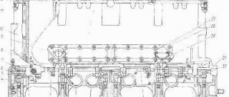
The coordinated operation of the high-pressure fuel pump and the gas distribution mechanism is ensured by installing the timing gears according to the marks in accordance with Figure 1.
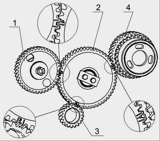
Rice. 1 — Diagram of installation of timing gears of the D-245 engine
1 - camshaft gear; 2 - intermediate gear; 3 - crankshaft gear; 4 – fuel pump drive gear.
Basic instructions for grinding in diesel valves D-245
Unscrew the nuts securing the rocker arm axle stands and remove the rocker arm axle with springs and rocker arms. Unscrew the head mounting bolts and remove the head. Dry the valve, remove the valve spring plate, valve spring, valve spring washers; Remove the sealing collar from the valve guide bushing.
Grind valves on special machines or on stands. Apply a paste prepared from a special composition to the chamfers of the valves or to the chamfers of the cylinder head sockets. The composition is diluted in diesel oil to a creamy state. To improve quality, it is recommended to add oleic or stearic fatty acid.
Continue grinding in valves D-245 of ZIL-5301 Bychok, GAZ-3309, MAZ-4370 Serration until a continuous matte belt with a width of at least 1.5 mm appears on the valve chamfer and on the valve seat chamfer, strip breaks or the presence of Risks are not allowed. The difference in the width of the belt is allowed to be no more than 0.5 mm.
After grinding in, it is recommended to wash the valves and engine block head. When assembling the head, lubricate the valve stem with engine oil. It is possible to grind valves manually, using a mechanic's tool, but the labor intensity of the grinding operation increases significantly.
Checking the tightening of the bolts securing the cylinder head of the D-245 diesel engine
Check the tightness of the bolts securing the D-245 cylinder head at the end of the run-in and every 40 thousand km on a warm diesel engine in the following order:
- remove the cap and cylinder head cover; - remove the rocker arm axle with rocker arms and struts; - using a torque wrench, check the tightness of all cylinder head mounting bolts in the sequence shown in Figure 2, and, if necessary, tighten them. Tightening torque - 220±10 Nm.
After checking the tightness of the cylinder head bolts, reinstall the rocker arm shaft and adjust the clearance between the valves and rocker arms.
Fig. 2 — Diagram of the sequence of tightening the cylinder head bolts
Checking the gap between valves and rocker arms of the D-245 engine
Check the gaps between the valves and rocker arms of the D-245 engine and, if necessary, adjust every 20 thousand km, as well as after removing the cylinder head, tightening the cylinder head bolts and when valve knocking occurs.
The gap between the rocker arm striker and the end of the valve stem when checking on an unheated diesel engine (water and oil temperature no more than 60 ºС) should be:
- intake valves - 0.25 mm; - exhaust valves - 0.45 mm.
When adjusting the gap between the end of the valve stem and the rocker arm on a cold diesel engine, set:
intake valves - 0.25 mm; exhaust valves - 0.45 mm
Adjust the gap between the rocker arm and the D-245 valve in the following sequence:
— remove the cylinder head cover cap and check the fastening of the rocker arm axle struts;
- turn the crankshaft until the valves in the first cylinder overlap (the intake valve of the first cylinder begins to open, and the exhaust valve begins to close) and adjust the clearances in the fourth, sixth, seventh and eighth valves (counting from the fan), then turn the crankshaft one revolution, installing overlap in the fourth cylinder, and adjust the clearances in the first, second, third and fifth valves.
To adjust the valve clearance, loosen the lock nut of the screw on the rocker arm of the adjustable valve and, turning the screw, set the required clearance using the feeler gauge between the rocker arm striker and the end of the valve stem. After setting the gap, tighten the lock nut. After adjusting the valve clearance, replace the cylinder head cover cap.
avtodisel.ru
Adjustment
We will do the valve adjustment according to my simplified method, using an injection pump. To adjust, we need a tool, such as a 32mm wrench to turn the crankshaft, a 14mm wrench to tighten the rocker arm lock nut, a screwdriver, a feeler gauge, a 19mm wrench.
Remove the top valve cover and unscrew the high pressure pipes to the injection pump. Using a 32 wrench, we turn the crankshaft by the pulley bolt and look at the top of the injection pump where the diesel fuel comes out, which means that is where the TDC of this cylinder is. Next, it’s a matter of technique, loosen the lock nut by 14 with a wrench, install the dipstick and make adjustments with a screwdriver. The dipstick should move snugly between the valve and the rocker. The gaps are as follows; 0.25 inlet, 0.30 inlet. The operating order of the cylinders is 1,3,4,2. In this way we adjust each cylinder of the engine in turn.
WATCH THE VIDEO
Valve adjustment D-245
Before you begin setting up the valves, you need to study the structure and features of this unit. The camshaft has five bearings and is driven by the crankshaft and timing gear. Five bushings are used as bearings, which are placed in the block bores using the pressing method.
The front bushing is made of aluminum, is located in the fan area, equipped with a thrust collar that secures the camshaft from axial shifts, the other bushings are made of cast iron. Steel valve tappets are coated with special cast iron, the spherical surface has a radius of 750 mm. The camshaft cams are slightly inclined.
To correctly adjust the D-245 (“Euro-2”) valves, it is necessary to take into account that the pusher rods are made of steel rod and have a spherical part that fits inside the pusher. The valve rocker arms are made of steel and swing on an axis fixed by 4 stands. The axis of these elements is hollow, equipped with eight radial holes that serve to deliver oil; the movement of the rocker arms is stopped by spacers in the form of springs.