Final drive of the DT-75V tractor
Next: Operational adjustment of the control mechanism of the DT-75V tractor
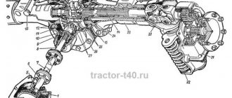
The final drive serves to transmit rotation from the rear axle shafts to the drive wheels (sprockets) of the tractor, as well as to increase the transmitted torque by further reducing the rotation speed of the driven shafts of the final drives.
The tractor is equipped with two final drives located on both sides of the rear axle. Each final drive consists of a pair of spur gears housed in a housing 28, which is bolted to the rear axle housing.
Rice. 1. Final drive: 1 - drive wheel; 2 — drive wheel shaft; 3—4—o-rings; 5 - spring; 6—rubber cover; 7 — protective visor; 8 — seal housing; 9 — roller bearing; 10 - cover; 11 — nut; 12—roller bearing; 13 - drive gear; 14 — safety lining; 15 — seal housing; 16 — bearing; 17 — washer; 18 — fit bolt; 19 — driven gear hub; 20 — bearing cup; 21 — ball bearing; 22 - bolt; 23 — washer; 24 — yoke fastening bolt; 25 - yoke; 26 — support mounting bolt; 27 — support; 28 — final drive housing; 29 — crown of the driven gear; 30 - bottom cover
The drive (small) gear, manufactured as one piece with the drive shaft, rotates in roller bearings. The inner race of the bearing is secured to the neck of the drive gear with a nut, and the outer race, pressed into the bore of the housing, is pressed by the belt of the cover bolted to the housing.
The axial movement of the inner race of the bearing in one direction is limited by the collar of the drive gear, and in the other - by the hub of the parking brake pulley. The outer race is fixed by the flange end of the final drive housing and the bore end of the seal housing, which is internally centered along the outer race of the bearing and bolted to the final drive housing. The flow of lubricant from the final drive housing to the brake compartments of the rear axle steering mechanism is prevented by a washer and a reinforced rubber cuff.
Torque from the drive gear to the drive wheel is transmitted through the driven gear and the drive wheel shaft.
The driven (large) gear is assembled. The crown is secured with tight-fitting bolts to the cylindrical belt of the hub mounted on the splines of the drive wheel shaft.
The drive wheel shaft is installed in the housing bores on bearings.
The inner race of the roller bearing is pressed onto the journal of the drive wheel and secured with a retaining ring installed in the annular groove on the journal of the shaft. The axial movement of the outer race is limited on the outside by the end of the centering collar of the seal body, and on the inside by a locking ring inserted into the annular groove of the body bore.
Read more: How to charge a battery-powered machine
Inside the seal housing there is a mechanical metal seal, consisting of a rubber boot, a spring and two steel o-rings. The protective visor prevents dirt from getting into the seal.
The outer race of the bearing is pressed into a cup installed in the bore of the final drive housing, and is clamped between the ends of the cup collar and the inner bore of the support with bolts that secure the support and cup to the final drive housing.
The inner race of the bearing is secured to the shaft journal with a special washer and three bolts.
A yoke is installed on the cylindrical end of the support, with the help of which the support is attached to the rear axle body with bolts. Additionally, the yoke is secured to the support with bolts.
A cover is attached to the bottom of the final drive housing. There are two holes in it, closed with plugs, one of which serves to control the oil level, and the other to drain the oil.
Pour oil through the neck located in the upper part of the housing. A breather is mounted in the neck plug.
A pad is attached to the final drive housing, protecting the housing from chafing by the track chain.
Maintenance of final drives consists of timely checking the oil level and adding it to the housings, replacing used oil, washing the final drive housing and periodically tightening the fasteners.
Fill the final drive housings with transmission oil to the level of the inspection plug hole. Replace used oil when switching to autumn-winter operation. After draining the used oil, tighten the drain plugs (a plug with a left-hand thread is installed on the right final drive) and fill the housings with diesel fuel. When the tractor is idling for 3-5 minutes, rinse the housings with diesel fuel, drain it, clean the magnets of the drain plugs from dirt and metal particles and fill the housings with fresh oil.
Periodically wash the filter packing of the filler pipe breathers.
When installing the final drive removed from the rear axle housing, follow these instructions.
With the final drive assembled and prepared for installation on the rear axle, pre-tighten the bolts so that the yoke turns tightly.
Before tightening the yoke bolts into the existing gap between the yokes and the rear axle, install a set of shims, having first measured the gap using a feeler gauge.
Tighten the bolts and bolts securing the final drives to the rear axle housing with a torque of 35-30 kgf m, the nuts of the fitting bolts securing the drive wheel with a torque of 25-30 kgf m. ... t 4.17. Tractor control mechanism
The tractor control mechanism includes levers, pedals and rods, with the help of which the power transmission mechanisms are controlled from the tractor driver’s cab. The tractor uses separate control of the rear axle brakes and introduces a hydraulic booster, which makes it easier to disengage the main clutch.
The tractor's rotation is controlled by levers. The force from the planetary brake control levers is transmitted through rods to the tension springs of the brake bands and releases the corresponding sun gears.
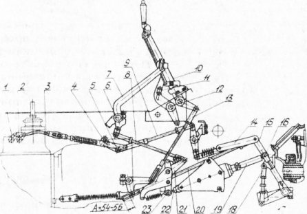
Rice. 2. Tractor control mechanism: 1,2 - gearbox locking rollers; 3,8,13 - thrust; 4—UKM brake lever; 5—UKM clutch lever; 6—clutch pedal axis; 7 - pedal; 9 - traction; 10.11 — control lever; 12 - axis; 14 — transfer rod; 15 — drive lever; 16—roller; 17 — splined lever; 18 — drive rod; 19 — power steering rod; 20—traction; 21 — lever; 22 — power steering spool rod; 23 — lever roller.
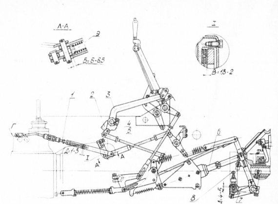
Rice. 3. Adjustment of the cardan brake: 1 - thrust; 2 - emphasis; 3 - pedal; 4 — lever; 5 - traction; 6 — power steering rod; 7 — cardan brake lever; 8 — thrust bolt; 9 - fork
4.17.1.6. Without changing the position of the power steering piston: - press the lever roller to the tip of the power steering piston, pressing the pressure pin flush with the tip; — place the clutch pedal in the extreme forward position; — without changing the position of the lever and pedal, install the rod; — adjust the brake rod of the torque multiplier so that gap B is 6-6.5 mm; — adjust the gearbox locking rod so that the pin of the rear locking roller rests on the surface D and the gap D is 1-3 mm; — adjust the cardan brake so that the gap A between the spring stop and the collar of the cardan brake lever is within 4-5 mm. Gap A is adjusted with a stop bolt.
Read more: Operational adjustment of the control mechanism of the DT-75V tractor
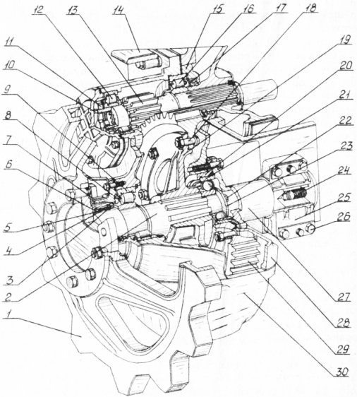
The planetary turning mechanism of the DT-75M tractor consists of two symmetrically located identical planetary devices for controlling the right and left track chains.
To turn the tractor, the tracks are turned off separately using planetary mechanisms, which, in combination with brakes, can act as friction clutches, i.e. disconnect and smoothly connect transmission shafts. The driving elements in the planetary turning mechanisms are ring gears 8 inside a common drum 4, and the driven elements are carriers 14, which are connected by shafts (half shafts) 1 to the drive gears of the final drives. On axes 13, fixed in the carriers, satellites 12 rotate, which connect the sun gears 11 to the ring gears.
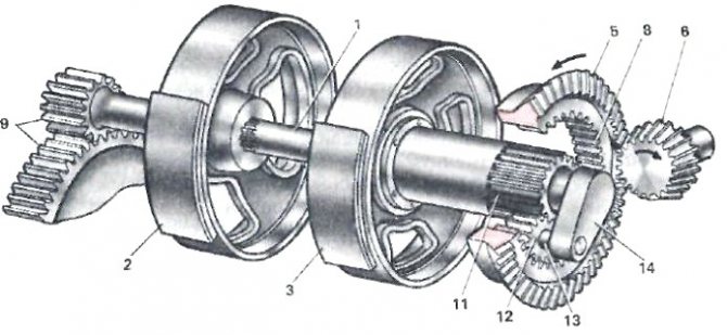
Rice. Components of the turning mechanism: 1 - shafts (half shafts); 2 — stopping brakes; 3 — sun gear brakes; 4 - drum; 5 and 6 - driven and driven bevel gears; 7 — secondary shaft of the gearbox; 8 — ring gears; 9 — final drive gears; 10 — driving sprockets; 11 — sun gears; 12 — satellites; 13 — satellite axes; 14 - drove.
When the tractor moves in a straight line, both sun gears are braked. The torque from the secondary shaft 7 of the gearbox is transmitted through the bevel gears 5 and 6 to the ring gears. The satellites they rotate roll along the sun gears and drag the carrier along with them through the axles. From the carriers through the axle shafts and final drive gears, the torque is transmitted to the drive sprockets 10, and they, rotating, rewind the tracks at equal speeds.
Read more: 0Xc0000428 windows 7 how to fix
To make a smooth turn of the tractor, for example to the left, you need to move the left lever towards you. When this happens, the brake band releases the brake pulley and the sun gear is released. When one of the sun gears is released, the satellites stop rolling over it, as it itself begins to rotate in the opposite direction. Therefore, the transmission of torque to the carrier stops, i.e., the caterpillar is disconnected from the transmission. However, due to the pushing force transmitted through the frame from another caterpillar, the disconnected caterpillar still continues to rewind, although at a lower speed. Therefore, the tractor will turn smoothly, especially when the resistance of the towed vehicles is low. In this case, the carrier, although disconnected from the ring gear, still continues to turn in the same direction, since it receives rotation from the lagging track through the sprocket and final drive.
To turn the tractor sharply, after turning off the sun gear brake, press pedal 17 of the driver brake. Then the brake band 12 stops the brake pulley 1 and brakes the shaft 2. The tractor makes a sharp turn. If you stop it with the brake, the sprocket and caterpillar will stop - the tractor will turn sharply in place.
When both sun gears are released simultaneously, the transmission of torque to the tracks stops and the tractor stops.
Planetary gears serve not only for turning, but also as additional gearboxes, which reduces the load on the gearbox parts and on the bevel gears of the rear axle.
The axle housing 1 is cast together with the gearbox housing. The middle compartment, where the planetary rotation mechanisms are located, and the cavity of the gearbox form a common oil bath. The side compartments are dry (the brakes are located here).
The driving bevel gear is manufactured together with the secondary shaft of the gearbox, and the driven one 26 is bolted to the flange of the ring gear drum 27, which rotates on ball bearings. The inner rings of these bearings rest on cups 24, pressed into the bores of the partitions. At the junction of the driven bevel gear and the flange of the ring gear drum, shims 25 are installed to adjust the engagement of the bevel gears.
In the drum 27 there are two internal ring gears, each of which is connected by three satellites 29 with its own sun gear 31. The teeth of the sun gears are cut at the ends of long hubs, which are inserted into cups 24 and rest on bronze bushings pressed into them.
The satellites rotate in needle bearings on axes 30, fixed in carriers 28, which are triangular-shaped steel castings. The inner ends of the shafts (half shafts) 37 are inserted into the splined hubs of the carriers. Their outer splined ends are connected to the drive gears 36 of the final drives.
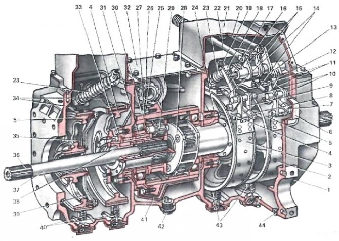
Rice. Drive axle of the DT-75MV tractor: 1 - body; 2 and 3 — brake bands; 4 — sun gear brake pulley; 5 — stopping brake pulley; 6, 21 and 32 - covers; 7 and 8 — adjusting nuts; 9, 12 and 18 - earrings; 10 - fingers; 11 and 13 — levers of the stopping brake mechanism; 14, 19, 20 and 22 - thrust; 15 and 16 — levers of the sun gear brake mechanism; 17 — lever axis; 23, 34 and 40 - springs; 24 - glass; 25 — adjusting shims; 26 — driven bevel gear; 27 — ring gear drum; 28 — drove; 29 — satellite; 30 — satellite axis; 31 — sun gear; 33 — oil seal; 35 and 39 — locking strips; 36 — final drive drive gear; 37 — shaft (axle shaft); 38 - seal; 41 — oil damping casing; 42 and 44 - plugs; 43 - support adjusting screws.
Bevel gears and planetary mechanisms are lubricated with transmission oil, which is poured into the middle compartment to the top mark on the rod fixed in the filler plug.
The oil damping casing 41 serves as an additional pan with a small oil level. This reduces the agitation, and therefore the heating of the oil in the middle compartment of the housing, and also reduces the throwing of mechanical impurities settling in the oil bath onto the parts. The penetration of oil from the middle compartment to the brakes is prevented by seals 33, made in the cups, and mechanical seals 38, installed in the hubs of the sun gears. The oil that has penetrated into the brake compartments is periodically drained by unscrewing plugs 44.
The planetary rotation mechanism is more complex and more expensive to produce than the friction mechanism, but it also has a number of advantages. It is more compact, which makes it possible to reduce the tractor track, is easier to control, more durable, with a better balance of power when turning. In addition, the planetary mechanism increases the transmission ratio.
contents .. 71 72 ..TRACTOR DT-75M.
FEATURES OF DISASSEMBLY AND ASSEMBLY OF THE A-41 ENGINE Tractor DT-75M.
Removing the cylinder head of the A-41 engine Remove the cylinder head only to troubleshoot parts of the liner-piston group, cylinder head gasket, valves, or replace the head itself:
a) drain the coolant from the engine cooling system;
b) disconnect all fuel lines from the head, clean their internal cavities from dust and dirt;
c) disconnect the decompressor rod and remove the cylinder head cap;
d) remove the nozzles, protecting the nozzles from impacts and clogging of the holes;
e) remove the gas distribution transmission mechanism and remove the rods;
f) loosen the cylinder head fastening nuts, following the same sequence as when tightening (Fig. 79), then unscrew them;
g) remove the cylinder head from the engine and check it, paying attention to the tightness of the plugs;
h) if necessary, carefully remove the cylinder head gasket to avoid damaging it;
i) check the condition of the cylinder liners and close the cylinder openings to protect them from dust and dirt.
Rice. 79. Sequence of tightening the cylinder head nuts
Grinding in engine valves A-41
Grind in valves if there is no tightness at the valve-valve seat interface:
a) clean the cylinder head from oil and carbon deposits and put marks on the valve plates so that when assembling, be sure to install them on their seats;
b) remove the valves, clean the valves and valve seats from
carbon deposits, rinse in kerosene and inspect to determine the extent of repair.
It is possible to restore the tightness of the valve by grinding in the presence of minor wear and small holes on the chamfers if the valve plate is not warped and there are no burns on the chamfers of the valve and seat. If these defects are present, grinding should be preceded by grinding the valve seats or replacing faulty ones with new ones;
c) clean the inlet and outlet channels of the cylinder head and rinse with diesel fuel;
d) mix the lapping paste thoroughly. The paste should consist of a mixture of micropowder M20 or M14 according to GOST 3647-71 with motor oil and stirred until creamy. In the absence of mechanical mixing, micropowder is capable of settling;
e) apply a thin, even layer of paste to the valve chamfer, lubricate the valve stem with clean engine oil and put it in place; f) lightly pressing the valve plate, turn the valve 1/3 turn (using a special tool), then in the opposite direction - 1/4 turn. Do not grind in a circular motion;
g) periodically lifting the valve and applying new portions of lapping paste to the chamfer, continue lapping until a continuous matte belt with a width of at least 1.5 mm appears on the chamfers of the valve and seat. Breaks in the matte strip and the presence of scratches on it are not allowed (Fig. 80);
h) after finishing the grinding, wash the valves and seats with kerosene, wipe dry, install the valves and springs. their places;
i) check the tightness of the valve grinding by pouring kerosene alternately into the inlet and outlet channels and keeping it in them for two minutes; leakage or seepage of kerosene when turning to any angle is not allowed. ,
It is allowed to check the quality of lapping using a pencil. To do this, apply six to eight lines across the chamfer of the ground valve with a soft graphite pencil, then carefully insert the valve into the seat and, pressing firmly, turn it 1/4 turn. All lines on the working chamfer must be erased.
If the test results are unsatisfactory, repeat the grinding.
Rice. 80. Location of the matte belt on the ground valve of the A-41 engine
contents .. 71 72 ..