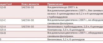
GAZ-66-11. Engine lubrication system ZMZ-66-06
The lubrication system (Fig. 13) is combined - under pressure, splashing and gravity. The oil in the engine oil sump is sucked into the oil pump 9 through the oil receiver 12. From the oil pump, oil under pressure is supplied through channels in the block to the full-flow filter 4, and from there to the main oil line 6 of the engine. From the main oil line, oil flows through channels in the cylinder block to the crankshaft main bearings and camshaft bearings. Through drillings in the crankshaft, oil from the main bearings enters the cavities of the connecting rod journals and through drillings in the connecting rod journals to the connecting rod bearings. In the cavities of the connecting rod journals, the oil undergoes additional purification due to centrifugal forces.
From the second and fourth camshaft bearings, oil flows through channels in the block and heads to the rocker arm axes. From the internal cavity of the rocker arm axis, oil flows through drillings to the rocker arm bearings; further along the grooves in the bushings, drillings in the rocker arms and adjusting screws - to the upper tips of the rods. Flowing down the rods, the oil enters the lower tips and, through the holes in the pushers, lubricates the pusher guide and its end.
The camshaft thrust flange is lubricated through a flat and holes in the front camshaft support. Drive gears - through a tube from the main oil line. The ignition distributor and oil pump drive and its gears are lubricated with oil coming from cavity 8 located between the fifth camshaft support journal and the plug in the cylinder block. Oil is supplied to other parts that require lubrication by splashing or gravity flow.
The oil pressure in the engine when the car is moving in direct gear at a speed of 55 km/h must be at least 2.5 kgf/cm2 with the oil cooler turned off and the engine well warmed up. When starting and warming up a cold engine, oil pressure can reach 5.5.5 kgf/cm2. When the oil pressure in the engine drops to 0.4. 0.8 kgf/cm2, the emergency oil pressure indicator lights up on the instrument panel.
It is permissible for the indicator to light up at a low crankshaft speed in idle mode. If the lubrication system is working properly, the indicator will go out when the rotation speed increases. If the indicator lights up at medium and high engine speeds, this indicates a malfunction, and until it is eliminated, further operation of the vehicle is not allowed.
At ambient temperatures above 20 °C and when driving
in particularly difficult conditions, it is necessary to turn on the oil cooler by opening the tap located on the left side of the engine. When the radiator is turned on, the faucet handle is directed along the axis of the hose. Oil enters the radiator only when the tap is open through the safety valve. This valve opens at a pressure of about 1 kgf/cm2. After passing through the radiator, the oil is drained into the oil sump.
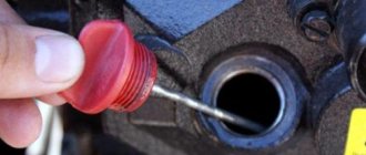
The oil sump is stamped from sheet steel and is attached to the lower plane of the block with studs. The crankcase flange is sealed with a cork gasket. At the bottom of the crankcase there is a drain plug sealed with a metal-asbestos gasket. The oil receiver is mesh, non-floating type.
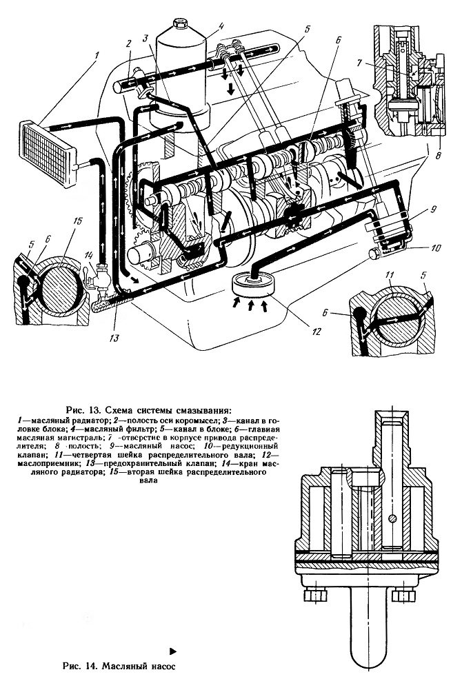
Rice. 13. Lubrication system diagram:
1—oil radiator; 2—cavity of the rocker arm axis; 3—channel in the block head; 4—oil filter; 5—channel in the block; 6—main oil line; 7 - hole in the distributor drive housing; 8 cavity; 9—oil pump; 10—reducing valve; 11—fourth journal of the camshaft; 12— oil receiver; 13—safety valve; 14—oil radiator valve; 15—second camshaft journal
Rice. 14. Oil pump
The oil pump (Fig. 14) is gear type, single-section, driven by the ignition distributor drive through the intermediate shaft. The pump body is made of aluminum alloy AL-4, the cover is made of cast iron SCh-18 GOST 1412-79. The cover contains a pressure relief valve that protects the lubrication system from excessive pressure. The valve is adjusted at the factory, and its adjustment during operation is prohibited.
The oil filter (Fig. 15) is full-flow with a replaceable paper filter element Re-gotmas 440A-1-06. It consists of the oil filter itself and its spacer. The spacer contains a bypass valve that is activated when the filter element is completely clogged. In this case, the oil enters the engine line, bypassing the filter element. The spacer is attached to the inlet pipe with a special fitting and sealed with a steam-nitrate gasket and a rubber ring.
When the filter element is clogged, oil flows from the spacer fitting through holes B into the safety valve area, opens the ball valve and, without cleaning, enters the spacer cavity, from where it goes into the main oil line. Thus, the bypass valve in the spacer protects the engine from running without oil, i.e., from a possible accident.
Checking the technical condition and repairing compressor parts
After disassembling the compressor to eliminate any malfunction, check the technical condition of its main parts.
If the wear of the cylinder exceeds the permissible level or its mirror is damaged, repair the cylinder to one of the repair dimensions indicated in the table. 2. According to these sizes, pistons and piston rings of repair sizes are produced.
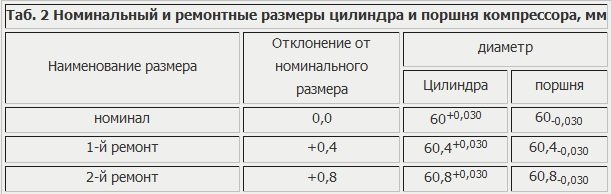
The piston repair size group is indicated by numbers on the piston bottom: “+ 0.4”, “+ 0.8”.
Oversize piston rings are marked:
one strip 10 mm wide corresponds to an increase in the diameter of the ring compared to the nominal by 0.4 mm, and two strips - by 0.8 mm.
When repairing the crankshaft, use liners of repair sizes, the thickness of which is increased by 0.15 and 0.3 mm. The repair size group of the liner is indicated by numbers on its outer side: “—0.3” and “—0.6” (these liners have a thickness of 1.9 -0.013 and 2.05 -0.013 mm, respectively).
If nicks or annular grooves are found on the cylinder head plate valves, replace them and grind new valves onto the seats to obtain continuous annular contact.
Piston pins, pistons and connecting rods are divided into four groups, which are sorted according to the diameters of the mating surfaces every 0.003 mm (Table 3).
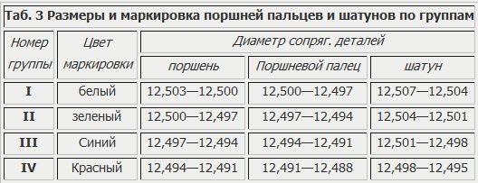
Marking places: piston - on the boss under the finger; piston pin - on the pin plug; connecting rod - on the head under the piston pin.
During assembly, it is allowed to install the pin and connecting rod of the adjacent group. The fingers to the connecting rod and piston are selected without lubrication at a temperature of 10—30°C. The correct selection of the piston pin to the connecting rod bushing is checked by touch. When pressed with your thumb, the piston pin without lubrication should move with some resistance in the bushing of the upper head of the connecting rod.
Compressor assembly. When assembling the piston with the pin-connecting rod set, lubricate the pin with clean engine oil.
When installing new rings, check the lock gap after installation in the cylinder. The gap should be 0.20-0.40 mm, and the ring should fit snugly around the entire circumference of the cylinder (check for clearance).
Check the height of the ring and the piston groove; the gap between the groove wall and the ring should be in the range of 0.035-0.080 mm. If the gap is smaller and the ring does not roll over the entire piston groove, the end of the ring can be lightly ground off using the finest sandpaper. Install the compression rings in the piston grooves with the grooves facing up, and their joints are separated by 180°.
While assembling the compressor, check that the crankshaft rotates easily. The torque required to turn it should not exceed; 0.2 kgm - before installing the connecting rod-piston group and 0.3 kgm - after installing this group and tightening the connecting rod bolts (but before installing the head).
When installing the intake valve seat, make sure that the narrower lip of the seat faces the valve. Through the upper hole of the head, check the valve stroke, which should be within 0.7-1.5 mm, and the discharge valve within 1.5-3.2 mm.
Compressor testing after repair. Testing should include running-in (no load), performance testing, leak testing and checking the operation of the unloading system.
The compressor is run-in for 20 minutes at 1200 - 1350 rpm of the crankshaft. The oil pressure entering the compressor should be 1.5-3.0 kg/cm2, the temperature should not be lower than +40˚С. The pressure of the air cooling the compressor should ensure that the temperature of the compressor head does not exceed 90˚.
The performance test is carried out at 1200 - 1350 rpm of the crankshaft and with air forced into a 23 liter tank. At a pressure in the tank of 6.5 kg/cm2, the cavity of the tank communicates with the atmosphere through a calibrated hole with a diameter of 1.0 and a length of 3 mm; under these conditions, the compressor must maintain a pressure in the tank of at least 6 kg/cm2 during continuous operation for 3 minutes. At the specified operating mode of the compressor, the ejection of oil with the forced air should not exceed 1 cm 3 per 5 min.
GAZ 2705 | Car lubrication
| Lubrication point name | Col. points | Col. lubricant material | Name of lubricant, oil | Periodicity | Work performed | ||
| TO-1 | TO-2 | CO | |||||
| Engine lubrication system | 1 | 6 l | See table. 11.5 | + | + | — | Change the oil and oil filter filter element (see section 4.1) - ZMZ-4025, 4026. Change the oil and oil filter - engines 4215, ZMZ-4061, 4063. |
| Ignition sensor-distributor rotor bushing (421 ZMZ-4025, 4026) | 1 | Engine oil | — | + | — | Lubricate the rotor bushing with 4-5 drops | |
| Gearbox housing | 1 | 1.2 l | At temperatures from -25° C to +40° C, Super T-3 oil. Duplicating oils: TSp-15K, Ufalub Unitrans, Devon SuperT. At temperatures from -40° C to +20° C oil "Lukoil TM-5" SAE 75W90 | — — | + +++ | — — | Check the level and, if necessary, top up to the level of the lower edge of the filler hole (for the plug located on the right side) or 7 mm below the level of the lower edge of the filler hole (for the plug located on the left side). Change the oil, clean the magnetic drain plug. |
| Cardan joint needle bearings | 3 | 60 g | Oil "Super T-3". Duplicating oils: Ufalub Unitras, Devon Super T | — | + | — | Change through grease nipples until fresh grease comes out from under all seals |
| Bushings and support bearings for steering knuckles | 2 | 25 g | Solidol S Backup lubricant Solidol Zh | + | + | — | Lubricate through the grease nipple until grease appears from under the support bearing seal and from the gap between the upper knuckle boss and the beam. If grease comes out from under the pin cover, it is necessary to tighten the cover mounting bolts and wash the pin joint with a mixture of transmission oil and kerosene in a 1:1 ratio through a grease nipple |
| Rear axle housing | 1 | 3.0 l (2.2* l) | At temperatures from -25° C to +40° C, Super T-3 oil. Duplicate oils: Ufalyub Unitrans, Devon SuperT. At temperatures from -40° C to +20° C, Lukoil TM5 oil SAE 75W90 | — — | + +++ | — — | Check the level and, if necessary, top up to the level of the control plug. Change the oil, clean the magnetic drain plug after operating at low temperatures on oil with the addition of diesel fuel, change the oil in the spring |
| Rear wheel bearings | 4 | 66 g | At temperatures from -25° C to +40° C, Super T-3 oil. Duplicate oils: Ufalyub Unitrans, Devon SuperT. At temperatures from -40° C to +20° C, Lukoil TM5 oil SAE 75W90 | — | +++ | — | When changing the oil in the rear axle, remove the hubs, wash them with kerosene, dry them, put 15 g of lubricant in each bearing and in the cavity between the working edges of the cuffs to 2/3 of the volume. Lubricate the working edges of the cuff with a thin layer of lubricant. |
| Front wheel hub bearings | 4 | 270 g | Litol-24. Backup lubricant LITA | — | +++ | — | Remove the hubs, wash with kerosene, dry, put fresh lubricant 15 g in the internal bearings, 10 g in the outer bearings, 110 g in the cavity of the hubs and in the cavity between the working edges of the cuffs, lubricating the edges with a thin layer of lubricant. Install the hubs and adjust the bearings |
| Shock absorbers | 4 | 0.28x4=112 g | AZh-12T. Duplicating fluid - spindle oil AU | — | — | — | Change fluid if necessary |
| Steering gear housing | 1 | 0.45-0.5 l | Oil “Super T-3” Duplicate oils: “Ufalub Unitrans”, “Devon Super T” | — | + | — | Check the level and top up if necessary. The oil level should be within 15mm down from the bottom edge of the filler hole |
| Steering shaft seal | 1 | 5 g | Litol-24 lubricant. Backup lubricant LITA | — | — | + | Move the lip of the seal and lubricate the working surface of the shaft |
| Steering universal joints | 4 | 7 g | Litol-24. Backup lubricants: Solidol S, Solidol Zh | — | — | + | Lubricate through the grease nipple until fresh grease appears. |
| Brake master cylinder refill reservoir | 1 | 0.52 l | Brake fluid "ROSDOT". Duplicating liquid "Tom" | — | — | + | Change the fluid twice a year (in spring) |
| Clutch master cylinder reservoir | 1 | 0.2 l | Brake fluid "ROSDOT". Duplicating liquid "Tom" | — | — | + | Change the fluid twice a year (in spring) |
| Battery terminals | 2 | 10 g | PVC grease or grease | — | — | + | Apply a thin layer |
| Locks and door lock drives (external and internal) | 28 | 40 g | VMGZ or MGE10A oil | — | + | + | |
| Door lock switches | 4 | 8 g | Litol-24. Backup lubricant LITA | — | — | + | Rinse before lubricating |
| Cab door limiters | 2 | 2 g | Litol-24. Backup lubricant LITA | — | — | + | Lubricate the lever as needed if squeaking occurs. |
| Rubbing surfaces of side door guides | 3 | 30 g | Litol-24. Backup lubricant LITA | — | + | — | Wipe before lubricating |
| Hood lock | 1 | 1 g | VMGZ or MGE10A oil | If necessary, if the latch jams | |||
| Hood lock drive | 1 | 15 g | Litol-24. Backup lubricant LITA | — | — | + | Rinse before lubricating. Lubricate the rubbing surfaces with a thin layer |
| Hood hinges | 2 | 2 g | VMGZ or MGE10A oil | — | — | + | Lubricate if necessary if squeaking occurs |
| Van and Bus Side Door Upper Roller Bearing | 1 | 20 g | Litol-24, LITA or CIATIM-201 | + | + | — | Apply lubricant |
| Engine cooling system | 1 | 9.7** l 11.5*** l | Coolants TOSOL-A40M, OZh-40, “Lena”, “Thermosol”, Brand A-40 | — | — | + | Check density during seasonal maintenance |
automn.ru
Compressor malfunctions and ways to eliminate them
Reduced performance:
– Air leakage through valves or piston rings
– Clogged compressor air filter (for vehicles without tire pressure control system)
Clean the filter media
– Low tension of drive belts
Adjust belt tension
The compressor overheats:
– Poor oil supply
Clean the oil lines and channels in the crankcase cover and the compressor crankshaft
– Carbon deposits on the piston and piston rings
Clean parts from carbon deposits
Throwing out oil with forced air:
– Wear of piston elbows or cylinder
– Failure of the oil supply seal to the compressor
Replace seal 14 (see Fig. 1) or rear compressor cover
– Broken seal spring
– Oil drain pipe clogged
Increased compressor knocking:
– Wear of pistons, pins or bearings
How much does gas 53 weigh - Car lover's blog
In the 60s of the last century, the plant, today called GAZ Group, began producing medium-duty trucks.
New power units, transmission mechanisms, cabin and body, and controls were installed on the trucks.
Models of series 52, 53, 66 formed a line of universal trucks, which, in the interests of the national economy, provided transportation in industry, for agricultural and construction needs.
Modifications and release history
The car was the most popular truck of the Union republics. There were 4 million conventional, dump truck and specialized vehicles operating on the country's roads.
In 1961-1967 GAZ-53F was produced. Six-cylinder 82 liters. With. The GAZ-11 engine with a four-speed gearbox ensured the transportation of 3,500 kg of cargo, consuming 24 liters of low-octane gasoline for a run of 100 km.
https://www.youtube.com/watch?v=LD35jDWONLk
By the planned release time of the model, the V-shaped eight-cylinder power unit was not in production.
For the 53F, the six-cylinder GAZ-11 was boosted, increasing the compression of the mixture. There was no ready-made hypoid rear axle, so they installed a mechanism with bevel gears from the 51A model (the car is shown in the photo).
Objectively, in terms of its technical characteristics, the GAZ-53F car was a transitional model between the 51A series (with a load of 2,500 kg) and the SAZ-53B series (with a load capacity of a ton more), which was achieved by an increased base to 3.7 m and new tires 8 ,25-20, mounted on steel disks.
The car was used not only as a dump truck, but also a sewage truck, fuel trucks and milk tankers were common.
The GAZ-53 was not a complete design; due to frequent failures of parts and mechanisms, it was not popular among drivers and repair workers of motor transport enterprises. The truck with a clearly weak engine and an unreliable axle was produced until 1967.
From 1964 to 1983, models of the 53 and 53A series with a cargo load of 3,500 and 4,000 kg hit the roads. More powerful power unit ZMZ-53 with 115 hp. With. ensured an increase in the speed parameter to 85 km/h with gasoline consumption of 25 liters per 100 km.
Differences between the 53A line and the 53
The car models have the following differences:
- reinforced front axle;
- new cardan design;
- more reliable steering gear design;
- new radiator grille;
- turn signals are duplicated by repeaters on the wings of the cabin;
- the presence of electric windshield wipers;
- cabin heating.
In 1973, model 53A was awarded the USSR State Quality Mark. Expanding the functionality of the vehicle, the production of chassis 53 01 for covered bodies and special equipment was launched.
Chassis 53 02 was a platform for the use of a dump truck body and was equipped with a power removal device for a hydraulic pump.
Trucks of models 53 50 and 53 70 were exported. The vehicles were readily purchased in Belgium, Finland, and in socialist countries. In Bulgaria and Cuba, trucks were assembled from kits supplied from GAZ.
Model 53 12 was produced from 1983 to 1992, as a further development of the 53rd line. The truck was equipped with an eight-cylinder ZMZ-511 engine.
Power parameter is 120 hp. With. made it possible to increase the load to 4.5 tons, and the speed indicator to 90 km/h.
Gasoline consumption increased to 30 liters, but provision was made for installing equipment for refueling with liquefied or compressed gas.
Technical characteristics of the basic on-board vehicle GAZ-53:
| Index | Unit change | Meaning |
| Production period | 1964-1983 | |
| Limit dimensions (length, width, height) | mm | 6 395, 2 380, 2 220 |
| Fuel consumption | l/100 km | 24 |
| Total places | 3 | |
| Load | kg | 4 000 |
| Fully loaded weight | kg | 7 400 |
| Base between wheel axles | mm | 3 700 |
| Ground clearance is minimal | mm | 265 |
| Speed | km/h | up to 85 |
| Power unit | ZMZ-53 | |
| Clutch mechanism | one disk, dry type, with lever drive | |
| checkpoint | by four steps | |
| Rear axle main gear | single, conical, hypoid | |
| Steering column | globoid worm and three-comb roller | |
| Tire size | 8,25-20 | |
| Brake device | drum-type mechanism on all axes, with hydraulic drive |
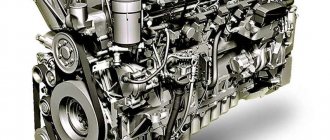
The engine on the GAZ-53 (ZMZ-53) truck is a V-shaped, eight-cylinder (two rows of four cylinders), carburetor type, operating on a four-stroke cycle.
The working volume of the internal combustion engine cylinders of the GAZ-53 car is 4.25 liters (with a cylinder cross-sectional size of 92 mm and piston strokes of 80 mm).
Technical specifications for power 115 hp. With. The GAZ-53 engine is started using a starter.
The nominal crankshaft revolutions per minute are 3,200. The mixture compression ratio is 6.7.
Systems and mechanisms
The cylinder block is made of casting from Al-4 alloy, after casting it is sealed by heat treatment and impregnation with synthetic resin. This is a monoblock V-shaped design with an angle along the cylinder axes of 90 degrees.
The cavities of the block and cast iron liners for the pistons form the water cooling jacket of the engine. The possibility of repair replacement of sleeves is provided (5 groups with letter designations). The clutch housing is secured to the end of the block with threaded rods.
The piston group is cast from Al-30 aluminum alloy. The piston is round in shape with a flat bottom; three grooves are cut into its body for oil scraper and compression rings.
Pistons are divided into 5 repair groups according to their own diameter (letter marking) and into 4 groups according to the diameter of the piston pin hole (color marking).
The block heads are made of Al-4 alloy. Valve seats are made of cast iron, guide bushings are made of copper-graphite ceramics. The block and cylinder heads are connected by threaded rods through gaskets made of asbestos board reinforced with steel.
The crankshaft is cast from cast iron, with connecting rod journals, bearings and counterweights formed on it. The shaft undergoes dynamic and static balancing.
Axial movement of the crankshaft is eliminated by two washers installed on either side of the first journal support. It is sealed in the block with oil-sinking grooves, oil seals and asbestos packing.
THIS IS INTERESTING: How much oil is in a box of VAZ 2107 5 mortar
The gas distribution mechanism with overhead valve installation ensures the intake of the working mixture into the cylinders and the exhaust of exhaust gas.
The device consists of: camshafts and gears, pushers, rocker arms, rods, valves, guide bushings and springs.
The camshaft is forged from steel. It has five bearing journals, cams, a gear drive for an oil pump and an ignition distributor.
The power system includes: a 90-liter gas tank, pipelines, a mechanically driven diaphragm pump, fuel filtering devices and a two-chamber K-126 carburetor - a device for preparing a fuel-air mixture.
The lubrication system supplies oil to the rubbing parts under pressure and gravity. Gear oil pump driven by a camshaft, full-flow oil filter, serviceable.
The air preparation filter is serviceable, inertial, with sedimentation of polluting particles in an oil bath.
Cooling system with water pump, closed type, liquid. It consists of a water jacket of the cylinder block, radiator, pump, thermostat, shutters, fan, fan casing, radiator cap and connecting hoses. Capacity – 22 liters. Contact ignition system.
Model 53 12
The truck is designed to transport cargo weighing up to 4,500 kg on asphalt and dirt roads. The machine allowed operation at temperatures from +40 to -40º C.
Option 53 12 is a deep modernization of the 53A model with better indicators in terms of fuel economy, repair regulations and safety.
Increasing the power of the power plant and the use of new radial tires made it possible to increase the dynamics and cross-country ability of the vehicle.
Cars of the 53 27 and 53 19 series ran on compressed and liquefied gas.
The ZMZ-53-11 power unit received a sectional oil pump, a full-flow filter device, new cylinder heads with an increased compression parameter, and the crankcase ventilation was switched to a closed circuit.
The car had strengthened: spring suspension, frame elements, cross member (beam) of the axle. It was possible to reduce exhaust toxicity by 19%.
In the future, the car will be equipped with a front-view triplex, a contactless ignition system, new lighting equipment, emergency signals, and a hydraulic vacuum booster with brake pressure distribution along the axes.
Dump truck
The truck was produced for transporting bulk cargo in the interests of agriculture and industry. Due to the hydraulic system, the unloading process was mechanized.
The capacity of the all-metal body platform is 5 cubic meters. A special mechanism allows mechanical unloading on one of the working sides.
The dump truck was produced on the GAZ-53 02 chassis with a frame shortened by 270 mm at the rear. The wheelbase remained the same. Equipped with a power take-off shaft.
The platform was equipped with a gear-type hydraulic pump, which, through a system of control valves, ensured the operation of a three-link hydraulic cylinder for lifting the body.
The rear hitch and towing devices have been moved to the sides of the frame.
Problematic issues of the entire series
The car series has the following disadvantages:
- short service life of the clutch and braking system;
- significant fuel consumption;
- unreliable: connection of parts of the cardan transmission, distributor and variator of the ignition coil;
- engine rear main bearing oil seal leaking.
The 53 Series medium-duty truck has proven to be a technically simple, reliable vehicle that is easy to drive. Durable cars with a discreet design can still be found on rural roads in the regions.
The machine can be serviced and repaired in a private garage, in a rural workshop, or in the field. Spare parts for cars are cheap and not in short supply.
When replacing oil and filter elements within the scheduled time frame, the engine life before overhaul can exceed 400 thousand km.
And in conclusion, let’s watch a video of a test drive of the GAZ-53 truck, and also find out the opinion of experts about the technical characteristics of the car:
Source: https://vipauto-barnaul.ru/ekspluatatsiya/skolko-vesit-gaz-53.html
Faulty power steering on the road
It happens that a breakdown takes you by surprise. If the hydraulic booster breaks down during a trip, you can continue the journey, but driving for such a long time is very dangerous. If you encounter such a breakdown, turn off the pump and drain the oil from the system. This will help reduce the force required to turn the steering wheel, but it will still be much greater than before. After such a trip, you will have to change the entire hydraulic power system.
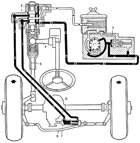
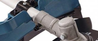
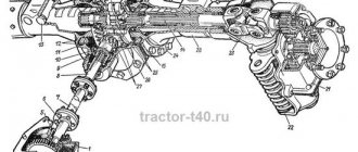
Steering diagram of a GAZ 66 with power steering
Adjusting and replacing the valves in the systems of a GAZ 66 car with a kung is not difficult if you know what needs to be unscrewed and where. It is worth considering that when replacing, it is best to use parts of the same series, especially for power steering, otherwise the serviceability of the mechanism cannot be guaranteed.
Power steering
Another mechanism of the GAZ 66, which has valves, is the power steering components. They also need to be checked occasionally for serviceability. The hydraulic booster allows the driver to turn the steering wheel without much effort despite the fact that the weight of the truck wheels is very large. This is possible due to the operation of the fluid flowing through the valves in the system. If one of the valves fails, the system will cease to function. It is very simple to understand when exactly it is worth checking the power steering: the steering wheel either does not turn at all or moves very tightly. This can only be corrected by overhauling and repairing the mechanism. Changing the oil can also solve the problem. The power steering includes:
- control valve;
- pump;
- power cylinder;
- oil lines.
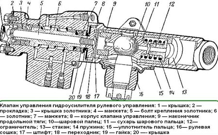
Diagram of the power steering valve Gas 66
Each of these parts should be checked for damage and replaced if necessary. The power steering mechanism is located directly on the engine.
2 smaller valves in the mechanism allow you to control the movement of oil in the system: one limits the movement of oil in the lines, and the second controls the amount of oil that approaches the control valve.
Oil moves throughout the system, so it must be changed over time, otherwise the pump may fail. After replacing one of the parts, the mechanism may need to be adjusted.
Design features of the GAZ 66 (ZMZ 511) engine
The gasoline internal combustion engine has a carburetor-type power supply system.
- Cylinders with a diameter of 92 mm are located at right angles.
- The distance between the axes of adjacent cylinders is 123 mm.
- The pistons drive the crankshaft.
- The engine is equipped with a closed liquid cooling system.
- The coolant circulates under the influence of a special pump - forced cooling.
- The lubrication system operates both under pressure and by spraying oil - combined.
The cylinder block is made from AL-4 aluminum alloy casting.
- The cylinder liners are made of special alloy cast iron, the diameter is 100 mm, the height is 153, respectively.
- The liners have lower fixation, the upper part is fixed under the influence of the cylinder head.
- At the bottom there are sealing rings made of copper.
- Thanks to the displacement of the lower part of the cylinder block housing by 75 millimeters relative to the axis of the crankshaft, its rigidity is significantly increased.
- The weight of the cylinder block body part is 44 kg.
Cast iron is used to make the crankshaft. Manufacturing material – high-strength cast iron VCh-50. The supporting main and connecting rod journals are hardened.
- Main journals with a diameter of 70 - 69.9 mm;
- Connecting rod – 60 – 59.9 mm.
In order to reduce the weight of the ZMZ 511 engine, connecting rods made by forging are used. The values of their parameters:
- Length – 156 mm;
- Weight – 0.86 kg;
- The diameter of the upper hole is 25 mm.
Piston parameters:
- Weight – 0.565 kg;
- Height – 51 mm;
- Diameter – 92 – 91.99 mm;
- The internal diameter of the piston pin is 16 mm;
- External – 25 mm.