Engines
The in-line sixes Mercedes-Benz OM457 LA with a volume of 11.97 liters, which are now installed on KAMAZ-5490 truck tractors, are reliable engines with a declared service life of 1 million km. They are assembled in Mannheim, Germany, at the Daimler AG engine plant. They are very economical, the service mileage reaches 80 thousand km. One of the disadvantages of this originally bus engine is that there is no power take-off to drive auxiliary gearboxes or hydraulic pumps. If you need to haul a dump semi-trailer or use any other equipment, you will have to equip the PTO gearbox (power take-off).
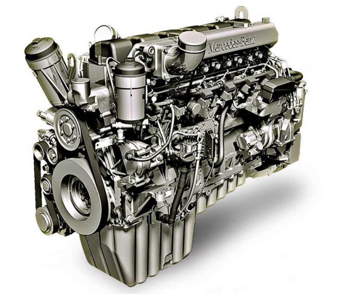
OM457 provides the road train with fuel consumption of 32–35 liters per 100 km
OM457 provides the road train with fuel consumption of 32–35 liters per 100 km
They planned to equip KAMAZ-5490 with the new promising G8 KAMAZ-750. This engine has a new block and common cast iron heads for each bank of cylinders. It also has a completely different dimension: the piston stroke was planned to be increased to 135 mm (and possibly up to 140 mm!), with a constant diameter of 120 mm (although it could have been increased by 5–10 mm), the working volume was about 13 liters. Power – up to 550 l. With. at 1900 rpm, torque over 2000 N.m at 1200–1400 rpm.
Experimental KAMAZ-750 engines were shown to us at the Scientific and Technical Center; the engines have already passed bench and road tests. But the use of Mercedes-Benz components on the KAMAZ-5490 still turned out to be optimal - with this machine, the Kama Automobile Plant rightly occupied its niche in the Russian market of tractors for interregional transportation.
Introduction
Machine maintenance is a set of preventive measures during the overhaul period aimed at preventing failures in units and components and reducing the wear rate of parts. Maintenance includes inspection and diagnostic, fastening, lubrication, filling, adjustment, electrical and other types of work.
Car maintenance has the goal: to ensure the constant technical serviceability of units and components in the car as a whole; maximize turnaround time; guarantee traffic safety; ensure minimal consumption of operating materials.
To achieve these goals, our country has adopted a planned preventative maintenance system, which provides for the mandatory implementation of a set set of works at a given frequency during the use, storage and transportation of vehicles. The technological process of servicing a car with a planned preventative system provides for a combination of mandatory work with work performed on demand, the need for which is determined as a result of checking the condition of the car. Maintenance of special equipment installed on the vehicle is carried out, whenever possible, simultaneously with maintenance of the chassis.
Depending on the volume of work and the frequency of their implementation, maintenance is divided into the following types: control inspection, daily maintenance, maintenance No. 1 (TO-1), maintenance No. 2 (TO-2), seasonal maintenance (SO). The objective of this course project is to become familiar with the vehicle maintenance system, draw up a technological map, determine the number and placement of workers, and also select technological equipment. Draw a drawing of the car in two projections indicating the number and location of the maintenance operation. And a diagram of the technological layout of the post with the arrangement of equipment and workers.
Main bridge
Another predictable and justified design solution is the use of a completely “Mercedes” drive axle, the Daimler HL6 model, which is installed on the Axor and Actros. This is 100% imported from Germany. The axle has a single 3.077 hypoid gearbox with a differential lock. Disc brake mechanisms.
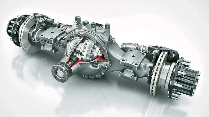
Daimler drive axle. It has a stamped-welded beam, brakes with ventilated discs, and a differential lock.
Daimler drive axle. It has a stamped-welded beam, brakes with ventilated discs, and a differential lock.
Daimler hypoid drive axles are used on 5490 truck tractors
Daimler hypoid drive axles are used on 5490 truck tractors
Technological map of KamAZ 53212 vehicle maintenance
Table 1
Technological map TO-1 of the KamAZ 53212 vehicle
| No. of work performed | Title and content of work | Service location | Number of service locations | Devices, tools, accessories, model, type | Technical requirements and instructions |
| General inspection | |||||
| 1 | Inspect the car and check the condition of the cabin, platform, glass, rear-view mirrors, tail, paint, license plates and rear-view mirrors | Top, front, back | — | — | The glass of the cab, headlights, sidelights, and direction indicators must be intact. The platform boards must not have cracks or kinks. The condition of license plates must meet the requirements of the Road Traffic Regulations. Rear view mirrors must be intact and correctly adjusted |
| 2 | Check the serviceability of the cab door locks, platform side locks, and towing device | Above, behind | — | Auto mechanic kit (large) I-148 (11) | The mechanisms of doors and platform side locks must be in good working order. The towing device must be securely fastened to the frame and its hinged bracket must be pinned |
| 3 | Check the operation of the windshield wipers, the windshield washer and the windshield defogger and heating device (in winter) | In the cockpit | 3 | — | The windshield wiper blades must fit snugly along the entire length of the edge to the surface of the windshield and move without jamming or stopping. During operation, the brushes should not touch the seal. The glass washing device must be in good working order and wash the entire glass surface evenly |
| Engine, including cooling and lubrication systems | |||||
| 4 | Inspect the condition and tightness of the cooling systems, engine lubrication, cabin heating system and starting heater | Up and down | 4 | — | Oil leakage at the mounting points of the oil filter and crankcase is not allowed. Leakage of coolant in the pipes and radiator is not allowed |
| 5 | If necessary, eliminate leaks in the pipelines of the cooling system, engine lubrication system, cabin heating system and starting heating | Same | 4 | Auto mechanic set (large) I-148 (11), pliers (12) | Leakage of oil, coolant and fuel can be eliminated by tightening nuts, clamps or replacing individual parts. |
| 6 | Check by ear the operation of the valve mechanism | Above | 1 | — | Let the engine listen to its operation. There should be no knocking in the valve mechanism if it is adjusted correctly. |
| 7 | If necessary, adjust the gaps between the valves and rocker arms | Same | 16 | Device for adjusting valves I801.14.000 (10), set of probes No. 2 (15) | Thermal clearances in the gas distribution mechanism are adjusted on a cold engine no earlier than 30 minutes after stopping. In each position, simultaneously adjust the valve clearances of two cylinders in the operating order: 1-5-4-2-6-3-7-8, turning the crankshaft by 900. Thermal clearances are adjusted in the following order: set the piston of the first cylinder to c. m.t. of the compression stroke, rotate the crankshaft in the direction of rotation (counterclockwise, when viewed from the flywheel side) through an angle of 600 (rotating the flywheel by the angular distance between two adjacent holes corresponds to between two adjacent holes corresponding to turning the crankshaft by 300), In this case, the valves of the 1st and 5th cylinders are closed (the valve rods can easily be turned by hand), check the tightening torque of the nuts securing the rocker arms of the adjustable cylinders and, if necessary, tighten them, to adjust the gap, loosen the adjusting screw nut, insert a feeler gauge into the gap and, Rotate the screw with a screwdriver to set the required gap. Hold the screw with a screwdriver, tighten the nut and check the gap. The gap should be 0.25-0.3mm for intake valves and 0.35-0.4mm for exhaust valves. |
| 8 | Check the fastening of the oil sump, exhaust pipes, muffler exhaust pipe flanges to the cylinder block and secure if necessary | Up and down | 3 | Auto mechanic set (large) I-148 (11), chisel (14), hammer (13). | Tighten the oil sump mounting nuts with a tightening torque of 1.5-1.7 kgf∙m, exhaust pipes 4.5-5.4 kgf∙m, exhaust pipe flanges of the muffler 4.5-5.4 kgf∙m |
| 9 | Check the mounting and, if necessary, secure the engine to the frame | Above | 1 | Auto mechanic kit (large) I-148 (11) | The nuts of the engine mounting bolts on the frame must be tightened and cottered. Carry out tightening with a tightening torque of 5.5 - 6 kgf∙m |
| 10 | Check the condition and tension of the generator and water pump drive belts | Above | 1 | Auto mechanic kit (large) I-148 (11) | The belt tension is ensured by moving the generator; a correctly tensioned belt, when pressing on the middle of the belt with a force of 4 kgf, the deflection should be 15-22 mm. |
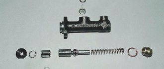
| Clutch | |||||
| 11 | Check the free play of the clutch pedal | In the cockpit | 1 | Ruler (16) | The pedal free play should be 6-12 mm |
| 12 | If necessary, adjust the free play of the clutch pedal | Same | 1 | Auto mechanic kit (large) I-148 (11) | The free play of the pedal is set by adjusting the gap between the piston and the master cylinder piston pusher. To adjust the gap between the piston and the master cylinder piston pusher, use the eccentric pin that connects the top eye of the pusher to the pedal lever. Rotate the eccentric pin so that the movement of the pedal from the top stop to the moment it touches the piston pusher is 6-12 mm, then tighten and cotter the castle nut. |
| 13 | Check the tightness of the hydraulic clutch release system | In the cabin and below | 1 | — | Liquid leakage in the main, working cylinder and pipeline is not allowed |
| 14 | If necessary, repair leaks in the clutch release piping | Same | 1 | Auto mechanic kit (large) I-148 (11) | Fluid leakage can be eliminated by tightening the nuts and replacing individual elements. |
| 15 | Check the fluid level in the compensation tank of the clutch master cylinder | Front | 1 | — | The liquid level in the tank from the top edge should be 15-20mm |
| 16 | If necessary, add fluid to the compensation tank of the clutch master cylinder | Same | 1 | — | The liquid level in the tank from the top edge should be 15-20mm |
| Transmission | |||||
| 17 | Check the fastening of the gearbox and its external parts | Up and down | — | Auto mechanic kit (large) I-148 (11) | Tighten the gearbox mounting bolts with a tightening torque of 5.5-6 kgf∙m |
| 18 | Check the operation of the gear shift mechanism with the vehicle stationary. | In the cockpit | 1 | — | Shifting gears must be done without jamming |
| Cardan transmission | |||||
| 19 | Check the fastening and, if necessary, secure the flanges of the cardan shafts, check the play in the articulated and splined joints of the cardan transmission | From below | 16 | Auto mechanic kit (large) I-148 (11) | Play in hinged and splined joints is not allowed; flanges should be tightened with a tightening torque of 12.5-14 kgf∙m |
| Rear (middle) axle | |||||
| 20 | Check the tightness of the connections of the rear (middle) axle, if necessary, eliminate the leak | From below | 2 | Auto mechanic kit (large) I-148 (11) | Oil leakage is not allowed. Eliminate leakage by tightening the nuts or replacing individual elements of the unit; tighten with a tightening torque of 1.5-1.7 kgf∙m |
| 21 | Check the fastening and, if necessary, tighten the fastening nuts of the gearbox housing and axle shaft flanges | Below and above | — | Auto mechanic kit (large) I-148 (11) | Tighten the gearbox mounting nuts with a tightening torque of 16-18 kgf∙m |
| Steering and front axle | |||||
| 22 | Check the power steering system for leaks | Above | — | — | Oil leakage in the oil line and in the pump is not allowed |
| 23 | If necessary, repair the leakage of the power steering system | Same | — | Auto mechanic kit (large) I-148 (11) | Oil leakage can be eliminated by tightening the nuts and replacing individual elements. |
| 24 | Check the fastening and cotter pins of the steering axle arm nuts. Troubleshoot if necessary | From below | 3 | Auto mechanic set (large) I-148 (11), pliers (12) | The nuts securing the steering axle arms must be tightened and cottered. Tighten the levers with a tightening torque of 36-40 kgf∙m. The levers should not have play in the socket and on the key. |
| 25 | Check the fastening and cotter pins of the ball pin nuts of the longitudinal and transverse steering rods. Troubleshoot if necessary | Same | 3 | Auto mechanic set (large) I-148 (11), pliers (12) | The ball pin nuts must be tightened and cottered. Backlash of fingers in conical sockets is not allowed. tighten the ball pins with a tightening torque of 9-10 kgf∙m |
| 26 | Check steering wheel play | In the cockpit | 1 | Device model NIIAT K-402 (8) | The check is carried out on a loaded car (without load) with the engine running at a speed of 600 - 1200 min-1, at normal tire pressure, set the front wheels straight. The free play of the wheels on a new car should not exceed 150. The maximum permissible free play is 200 |
| 27 | Check the play in the steering rod joints | Below and in the cockpit | 3 | — | Play in the steering rod joints must be checked by the relative movement of the ball pins and rod ends or heads when the steering wheel is sharply turned in both directions. Play in steering rod joints is not allowed. |
| Brake system | |||||
| 28 | Check the serviceability of the brake system using an external inspection and according to the readings of standard instruments. | Below and in the cockpit | — | — | The pressure created by the compressor should be 6.2-7.5 kgf/cm2. When you press the brake pedal, the pressure should drop sharply by no more than 0.5 kgf/cm2 |
| 29 | Check the condition and tightness of the brake system pipelines and devices and, if necessary, correct the malfunction | Up and down | — | Auto mechanic kit (large) I-148 (11) | Depressurization of the brake system is not acceptable. Depressurization can be eliminated by tightening the nuts or replacing individual elements of the system |
| 30 | Check and, if necessary, adjust the stroke of the brake chamber rods | From below | 6 | Auto mechanic set (large) I-148 (11), pliers (12), ruler (16) | The stroke of the rods should be no more than 40mm. Carry out the check in the following order: install a ruler parallel to the rod, resting its end against the brake chamber body, mark the location of the extreme point. Press the brake pedal all the way (pressure in the pneumatic drive is at least 6.2 kgf/cm2, the drums are cold, the parking brake system is turned off), mark the location of the same point. The difference between the obtained values is the stroke value of the rod. The stroke of the rod is adjusted by turning the worm axis of the adjusting lever, after unscrewing the lock two or three turns. Rotate the axis to set the smallest stroke |
| 31 | Change the alcohol in the freeze protector | Above | 1 | Auto mechanic kit (large) I-148 (11) | Drain sediment from the filter housing. To fill alcohol and control its level, release the rod handle to the lower position and fix it by turning it 900, unscrew the plug with the level indicator, pour alcohol and close the filler hole, turn on the fuse |
| Chassis | |||||
| 32 | Inspect the condition of the frame, components and suspension parts | From below | — | — | There should be no loosening of rivet joints, cracks, spars or cross members. |
| 33 | Check the fastening of the spring ladders | Above | — | Auto mechanic's set (large) I-148 (11), wrench for spring stepladder nuts model I-314 (7) | tighten stepladders with a tightening torque of the front ones - 25-30 kgf∙m, back 95-105 kgf∙m |
| 34 | Check wheel fastening | Same | 30 | Impact wrench for wheel nuts model I-303M (6) or wheel wrench 535M (9) | Tighten the nuts with a torque of 25 - 30 kgf∙m evenly, in one, two or three steps, starting from the top. |
| 35 | Check the condition of the tires and the air pressure in them, remove foreign objects stuck in the tread and between the paired wheels | Same | 10 | Air dispensing column model TsKB S-401 (1) or tip with pressure gauge model 458 (2), pliers (12) | The tire should not have cracks, tears, or swelling. The tire valve must have a cap. Air pressure 5.3-7.3 kgf/cm2. The remaining tread depth in the center of the treadmill must be at least 1.0 mm |
| Cabin and platform | |||||
| 36 | Check the condition and operation of the locking mechanism, stop-limiter and safety device | Above | — | — | The locking mechanism and safety devices must be in good condition |
| 37 | Check the fastening of the platform to the vehicle frame and secure if necessary | Same | — | Auto mechanic kit (large) I-148 (11) | tighten the platform fastening nuts with a tightening torque of 18-21 kgf∙m |
| 38 | Check the fastening of the footrests and mudguards, secure if necessary | Same | — | Auto mechanic kit (large) I-148 (11) | Tighten the footrests with a tightening torque of 1.5-2.5 kgf∙m, mudguards with a tightening torque of 1-2 kgf∙m |
| 39 | Inspect the surface of the cabin and platform, if necessary, clean areas of corrosion and apply a protective coating | Top, front, back | — | Wire brush | Rust, paint peeling, cracks are not allowed |
| Supply system | |||||
| 40 | Inspect the condition and tightness of the power system: low pressure fuel pump, fine fuel filter, fuel tank, fuel sediment filter, fuel line connections, high pressure fuel pump and fine filter | Above | — | — | Fuel leakage in the instruments and fuel lines of the system is not allowed. Fuel lines must not be bent or cracked |
| 41 | If necessary, eliminate leaks in devices and connections of fuel lines of the power supply system | Same | — | Auto mechanic set (large) I-148 (11), pliers (12) | Fuel leakage from instruments and fuel system connections is eliminated by tightening individual connection elements. tighten with a tightening torque of 4.5-5.4 kgf∙m |
| Electrical equipment | |||||
| 42 | Check the operation of the horn, headlights, sidelights, rear light, brake light, instrument panel lamps and direction indicators | In the cabin and above, front, rear | — | — | All lamps should produce light without blinking, and the sound signal should be sharp without rattling or wheezing. |
| 43 | If necessary, replace faulty headlight, sidelight and rear light bulbs | In the front and in the back | — | Auto mechanic kit (large) I-148 (11) sanding paper (19) | When replacing lamps, it is necessary to clean the contacts of the sockets. |
| 44 | Check the condition and fastening of electrical wires | In the cabin, front, top, rear | — | Auto mechanic set (large) I-148 (11), pliers (12) | Electrical wires must be in good condition and securely fastened |
| 45 | If necessary, insulate damaged areas of electrical wires (up to 200 mm long) | Same | — | Pliers (12), mounting knife, insulating tape | Damaged areas of electrical wires must be carefully insulated |
| 46 | Check and, if necessary, secure the generator | Above | 1 | Auto mechanic kit (large) I-148 (12) | — |
| 47 | Clean the surface of the battery from dust, dirt and electrolyte. | Above | 1 | Rubber gloves (17), rags (20), bath with a solution of ammonia or soda ash, brush (18) | The surface of the battery must be dry and clean. The electrolyte must be wiped with a rag soaked in a solution of ammonia or soda ash. |
| 48 | Clean the ventilation holes in the battery plugs | Same | 6 | Battery plug wrench (17), wooden stick Æ 1.5 mm, rags (20), rubber gloves (17) | — |
| 49 | Check the electrolyte level in the battery and, if necessary, add distilled water | Same | 6 | Level measuring tube (17), rubber gloves (17), rubber bulb (17) | The electrolyte level in the cells should be 10-15mm above the top edge of the safety grid |
| 50 | Check the fastening and condition of the wire tips with the battery terminals | Same | 2 | Auto mechanic kit (large) I-148 (11) | The terminals of the lugs must make good electrical contact |
| 51 | If necessary, clean and lubricate the battery terminals and wire ends | Same | 2 | Rags (20), sanding paper (19) | Clean oxidized battery terminals and wire ends and apply non-contact surfaces with Litol 24 lubricant GOST 21150-87 |
| Lubrication and cleaning work | |||||
| 52 | Check the oil level in the engine crankcase | Above | 1 | Oil dipstick and rag (20) | Check the oil level with the engine not running in the following order: remove and wipe the dipstick, insert it into the socket until it stops and remove it. The oil level should reach the upper mark |
| 53 | If necessary, add oil in the crankcase to normal levels. | Same | 1 | Oil dispenser model 367МЗ (4), rags (20) | Use oil M-10G2k, GOST 8581-78, in winter - M-8G2k, GOST 8581-78, all-season - DV-ASp-10V |
| 54 | Check the oil level in the power steering pump reservoir | Same | 1 | — | The oil level should be between the marks on the indicator. |
| 55 | If necessary, add oil in the power steering reservoir to the correct level. | Same | 1 | Rags (20) | Add oil to the specified level with the engine running at minimum crankshaft speed. Oil for the hydraulic system of a car, grade “R”. |
| 56 | Check the oil level in the gearbox housing | From below | 1 | Auto mechanic kit (large) I-148 (11), rags (20) | Unscrew and wipe the oil dipstick, insert it into the socket until it stops and remove it. The oil level should reach the upper mark |
| 57 | If necessary, top up the gearbox housing to the correct level. | Same | 1 | Auto mechanic kit (large) I-148 (20), installation for filling car units with transmission oil model 3161 (3) | TSp-15k, GOST 23652 - 79 (at temperatures not lower than minus 300C), TM5-12RK, TU38.101.844 - 80 (at temperatures up to minus 500C). |
| 58 | Check the oil level in the rear (middle) axle housing | Same | 2 | Auto mechanic kit (large) I-148 (11) | The oil in the rear axle housing should be at the level of the inspection hole |
| 59 | If necessary, add oil to the rear (middle) axle housing to the correct level. | Same | 2 | Auto mechanic kit (large) I-148 (11), installation for filling car units with gear oil 3161 (3) | TSp-15k, GOST 23652 - 79 (at temperatures not lower than minus 300C), TN5-12RK, TU38.101.844 - 80 (at temperatures up to minus 500C). |
| 60 | Clean the breathers of the gearbox and rear (middle) axle | Below and above | 3 | Rags (20), wire with a diameter of 1.5 mm | — |
| 61 | Lubricate the front axle steering knuckle pins | From below | 4 | Solidolon blower model 390 (5) | Lubricant Litol - 24, GOST 21150 - 87. Substitutes: solid oil Zh, GOST 1033 - 79 or solid oil S, GOST 4366 - 76, Lubricate through grease nipples until fresh grease is squeezed out |
| 62 | Lubricate the front spring pins | Front | 2 | Same | Same |
| 63 | Steering rod joints | From below | 4 | Same | Same |
| 64 | Lubricate the brake adjustment levers | Same | 6 | Same | Same |
| 65 | Expansion fist shaft bushings | Same | 6 | Same | Lubricant Litol - 24, GOST 21150 - 87. Substitutes: solid oil Zh, GOST 1033 - 79 or solid oil S, GOST 4366 - 76. Lubricate through grease nipples, making no more than five strokes with a syringe |
| Organizational work. Preparation of documents and quality control of vehicle maintenance | |||||
| 66 | Place the vehicle at the service station. | Fast | — | — | The vehicle must be installed at the work station only after labor-intensive repairs, cleaning and washing work, and in a clean and dry condition. |
| 67 | Enter data on the completion of TO1 into the vehicle maintenance and current repair record sheet. | office desk | — | — | — |
| 68 | Provide assistance and monitor the quality of performers’ work. | — | — | The operation is performed by a master or senior mechanic. | |
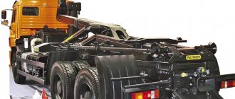
Cabin
They could very well make their own mainline tractor in Chelny on their own. Under the same index 5490, work was underway on a completely different car: with a cabin developed on the instructions of KAMAZ OJSC by the South Korean engineering company DMEC, part of Kia Motors, which, in turn, has been owned by Hyundai Corporation since the late 90s. And Hyundai Motor is seriously cooperating with Daimler. Prototypes of the entire family of these cabins were already ready: wide and narrow, with a sleeping bag and daytime, short ones. The cabins turned out to be very good, but the interior was not clear. Now the Mercedes-Benz Axor cab is installed on the KAMAZ-5490.
Read more about the fourth generation KAMAZ-5490 at this link.
Photo: Nikolay Mordovtsev, Vitaly Zudin
New generation KAMAZ: almost everything is imported
Bibliography
1. Technology for performing routine maintenance of the first and second maintenance of the GAZ 53A car.
2. Central design and technology bureau for the implementation of new technology and scientific research in road transport (CENTRAVTOTECH). - M. Transport, 1978. - 136 p.
3. Regulations on the maintenance and repair of rolling stock of road transport Approved on September 20, 1984. M.: Transport 1986, 73 p.
4. Practical guide to the maintenance and repair of KamAZ P69 vehicles, type 6X4/ E.A. Mashkov. - M.: Mechanical Engineering, 1994. - 243 pp.: ill.
5. Sheet of garage and technological equipment for motor transport enterprises of different capacities. S.A. Nevsky. - M.: Publishing house. CENTRTRUDAVTOTRANS, 2000. - 93 p.