content .. 51 52 59 ..
Chapter 5
BRAKE SYSTEMS FOR MAZ-64227, MA3-54322 CARS
Device
The vehicles are equipped with service, parking, spare and auxiliary brake systems, as well as brake devices for connecting the brake system of a semi-trailer with one- and two-wire pneumatic drives and outputs for supplying other consumers with compressed air.
The service brake system acts on the brake mechanisms of all wheels of the car. The drive mechanisms are pneumatic with separate braking of the front and rear wheels.
The parking and spare brake systems act on the brake mechanisms of the middle (for the MAZ-64227) and rear axles, which are activated using brake chambers with spring energy accumulators. Control is carried out using a crane in the driver's cabin.
The parking brake system also serves as a backup brake system, which is designed to brake the vehicle in the event of a complete or partial failure of the service brake system.
When the parking brake system is activated, the control valve handle is set (by turning) to its extreme fixed position. The compressed air that compresses the power springs of the energy accumulators is released into the atmosphere, and the springs activate the brake mechanisms.
When the emergency brake system is activated, the parking brake control valve handle is held in any intermediate non-fixed position.
As the angle of rotation of the handle increases, the braking intensity increases due to a decrease in air pressure compressing the springs of the energy accumulators.
The auxiliary braking system acts on the vehicle's transmission by creating back pressure in the exhaust system using a pneumatically driven throttle valve and is designed to slow down the vehicle on long descents of mountain roads. When turning the valve, the fuel supply is simultaneously turned off.
When the tractor vehicle is braked by the working or parking (spare) systems, the semi-trailer is simultaneously braked. Braking of the semi-trailer MA3-9398 and MA3-9389 also occurs when the auxiliary brake system of the MAZ-64227 vehicle is turned on.
Brakes
Drum type (see Fig. 57 and 72), with two internal shoes. Brake linings measuring 420x160xx17 are attached to the pads with brass rivets. The brake drum 29 (see Fig. 57) is attached to the wheel hub 17 with bolts 30. At the end of the expansion knuckle shaft 24 there is a worm-type adjusting lever (Fig. 92) connected to the brake chamber rod.
To prevent lubricant from entering the brake mechanisms in the expansion brackets
The front and rear brake cams are equipped with rubber O-rings.
Diaphragm brake chambers are designed to activate the brake mechanisms of the front wheels of a car when the service brake system is activated.
Brake chambers with spring energy accumulators (Fig. 93) are designed to activate the brake mechanisms of the wheels of the rear and middle (for MAZ-64227) axles when the service, parking and spare brake systems are activated.
When the service brake system is turned on, the brake mechanisms are actuated by the rods of 10 diaphragm brake chambers, the design and operating principle of which are practically no different from the front brake chambers.
When the parking brake system is turned on, compressed air is released from the cavity under the piston 6. The piston, under the action of the power spring 7, moves down and moves the pusher 4, which, through the thrust bearing 9, acts on the diaphragm 3 and the brake chamber rod 10, resulting in the vehicle braking.
When the parking brake system is turned off, compressed air is supplied under the piston 6, which, together with the pusher, moves upward, compressing the spring and allowing the brake chamber rod to return to its original position under the action of the return spring 1.
When braking by the reserve system, the air from the cylinders of the energy accumulators is not completely released, but only to the extent of the required braking efficiency of the vehicle, which corresponds to the intermediate positions of the control valve handle. Thus, the braking efficiency depends on the angle of rotation of the crane handle.
The mechanism of the throttle-type auxiliary brake system (Fig. 94) with a damper installed in the engine exhaust pipe in front of the muffler consists of a housing
1 and the damper 2, fixed to the axis 3. The rotary lever 4, connected to the rod of the drive pneumatic cylinder, is also fixed to the damper axis. Lever 4 and associated damper
2 have two fixed positions. When the auxiliary brake is turned off, the damper is installed along the exhaust gas flow, and when the brake is applied, it is perpendicular to the gas flow, creating back pressure at the exhaust. At the same time, the fuel supply is turned off using a pneumatic cylinder connected to the engine stop bracket.
The pneumatic cylinder (Fig. 95) is designed to control the flap of the auxiliary brake system mechanism. When the auxiliary brake system is turned on, compressed air enters the space above the piston and, overcoming the resistance of the return springs, moves the piston and rod 8, which is connected to the damper control lever of the mechanism. The piston returns to its original position under the action of the return spring.
Rice. 92. Adjustment lever: 1 - body; 2 cover; 3 - worm; 4 - gear; 5 — locking plate; 6 - bolt
content .. 51 52 59 ..
Features of the MAZ brake system
Page 1 of 2
The vehicles are equipped with service, parking, spare and auxiliary brake systems, as well as devices for connecting the brake system of a semi-trailer with a two-wire pneumatic drive and outputs for supplying other consumers with compressed air.
The service brake system acts on the brake mechanisms of all wheels of the car. The drive mechanisms are pneumatic with separate braking of the front and rear wheels.
Electro-pneumatic pressure modulators of the anti-lock braking system (ABS) can be installed in the brake drive.
The parking and spare brake systems act on the brake mechanisms of the middle and rear axles,
which are activated using brake chambers with spring energy accumulators (Fig. 1, 2). Control is carried out using a crane in the driver's cabin.
The parking brake system also serves as a spare one. It is designed to brake the vehicle in the event of a complete or partial failure of the service brake system.
When the parking brake system is activated, the control valve handle is set (by turning) to its extreme fixed position. The compressed air that compresses the power springs of energy accumulators is released into the atmosphere, and the spring activates the brake mechanisms.
When the emergency brake system is activated, the parking brake control valve handle is held in any intermediate non-fixed position.
As the angle of rotation of the handle increases, the braking intensity increases due to a decrease in air pressure compressing the springs of the energy accumulators.
1) The parking brake system acts on the brake mechanisms of the middle and rear axles, which are actuated by brake chambers with spring energy accumulators. Control is carried out using a crane in the driver's cabin.
The same system serves as a spare one. It is designed to brake the vehicle in the event of a complete or partial failure of the service brake system. When the emergency brake system is turned on, the parking brake control valve handle is held by the driver in any intermediate non-fixed position. As the angle of rotation of the handle increases, the intensity of braking increases.
2) The parking system consists of two independent systems: the main one, acting through the transmission on the wheels of the middle and rear axles of the car, and an additional one, acting on the wheels of the rear axle and controlling the brakes of the trailer.
The main parking brake system includes a drum brake (Fig. 3), installed on the output shaft of the transfer case in the drive of the middle and rear axles, and a mechanical, manually controlled multi-pass brake drive (Fig. 4).
The auxiliary parking brake system includes the service brakes of the vehicle's rear axle, the drive circuit for the trailer brakes and the vehicle's rear axle brakes, and a manually operated valve.
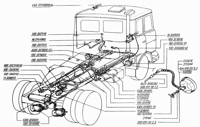
The valve has a tracking action based on the angle of rotation of the handle, which allows you to adjust the intensity of braking when using this brake system as a spare one. An additional parking brake system is used for short-term braking of a road train together with the main braking system on roads with a slope of more than 12%.
The auxiliary brake system acts on the vehicle's transmission by creating back pressure in the exhaust system using an air-actuated throttle body. It is designed to slow down the car on long descents of mountain roads. When turning the valve, the fuel supply is simultaneously turned off.
When the tractor vehicle is braked by the working or parking (spare) systems, the semi-trailer is simultaneously braked.
6.3. Brake systems. Brake repair.
Brake repair. The parts that suffer the most wear in service brakes are the friction linings and working surfaces of the drums, as well as the bushings and journals of the expansion knuckles and the axles of the pads. The design of the brake mechanisms provides for an easily removable brake drum and the ability to visually determine the condition of the brake linings through hatches in panels 21 (see Fig. 56). To disassemble the service brake, you need to jack up the wheel, remove the tire and, unscrewing the nuts, remove the disc from the studs 19. Then you need to screw two M16 bolts into the dismantling threaded holes of the drum 29 and remove the drum by evenly screwing in the bolts. After this, you need to remove the tension springs 23, unscrew the bolt 20 and, moving the pads 28 away from the expansion knuckle 24, remove them from the axles 22. Disassembling the front wheel brake is given in section “4.4 Front axle and steering rods. Device". Friction linings must be replaced if the distance from the surface of the lining to the head of the rivets remains less than 1.0 mm.
Installation of new linings and riveting them to the blocks is carried out in a special device that ensures a tight fit of the lining to the surface of the block. The local gap between the block and the lining should not be more than 0.3 mm; the shape of the rivet, its dimensions, as well as the dimensions of the hole for the rivet in the lining are shown in Fig. 113. The riveting is done from the block side; we hide the head of the rivet and should lie on a mandrel that ensures that the head retains its shape during the riveting process. Riveting can be done in a vice using a simple tool. After riveting the linings, the pads assembled with the linings must be processed in pairs along the outer diameter to the nominal size, if the drum has not been bored to the repair size. If the drum is bored to one of the repair sizes, then the pads assembled with linings must be machined to the same repair size number (Table 13).
The processing of the pads is carried out on a lathe using the R-114 installation, which ensures the correct placement of a pair of pads. If necessary, brake drums are bored to one of the repair dimensions indicated in Table 13. Wear of the expansion knuckle journals is allowed up to a diameter of 39.75 mm, and the expansion knuckle bushings - up to 40.10 mm. If these surfaces are worn beyond the specified values, the journals are welded and machined to a nominal diameter of 40±0.075 mm, and the bushings are replaced with new ones. Wear of the support journals of the pad axles is allowed up to a diameter of 31.88 mm. The wheel brake is assembled in the reverse order of disassembly. When installing the pads, you need to lubricate the axles 22 with Litol-24 grease GOST 21150-75.


