Crane arm
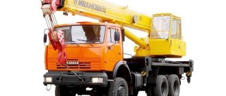
The crane manipulator is a hydraulic crane with a full-rotating telescopic boom with a cable suspension for lifting loads.
Such structures are valuable on construction sites due to a number of advantages and special properties of CMU.
The ability to accurately and clearly designed unloading and loading, without jolts and shocks, onto a pre-prepared site plays an important role.
The manipulator crane can lift or lower a load onto the site behind certain obstacles in the form of fences, walls or any other structures or large objects.
The CMU can also easily cope with loads that are located at a level below the device itself, for example in a well or trench.
Modern cranes are equipped with a system for monitoring the weight of the load being lifted, using sensors for boom length and tilt angle. The security system will signal if the maximum permissible load weight is exceeded.
As a rule, the manipulator is equipped with additional rear supports, which help relieve the load on the vehicle frame.
Loader cranes equipped with a working platform (cradle)
Recently, loader cranes have begun to be equipped with additional equipment. Basically it is a drilling rig and a cradle for lifting people. In this version, manipulator cranes have today become one of the most advanced technical solutions, allowing to increase the intensity of the use of equipment for transporting goods, to minimize manual labor during loading and unloading, while reducing not only the number of employed people, but also the number of trucks per construction site.
Today, cranes can be equipped with hook suspensions, lifting grips for piece goods, grabs for bulk and small-piece materials, fork and tong grips with rotators, drills, disc cutters, cradles for lifting people and installation work at height, etc.
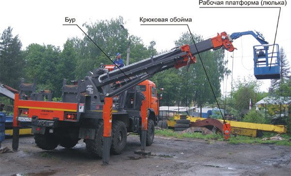
Fig.1 A crane equipped with a cradle (using the example of the Korean CMU model SA-040C)
The most common additional equipment for loader cranes are cradles for lifting people. As a rule, these are cradles with a load capacity of no more than 250 kg, with the gravitational principle of leveling and hydraulic blocking of the leveling mechanism in the working position of the cradle.
Figure 1 shows a crane equipped with drilling equipment and a cradle for lifting people. All equipment is mounted on a KAMAZ-43118 chassis, crane-manipulator unit from a Korean company, model SA-040C.
The vast majority of cranes with cradle supplied to Russia from South Korea do not comply with Rostechnadzor regulations. In other words, such cranes with a cradle cannot be operated legally and cannot be registered with Rostechnadzor.
CJSC ETC KROS equips cranes with a working platform (cradle) with a safety system for the purpose of using it as a lift with registration with Rostechnadzor. After equipping the working platform on the crane, the requirements of GOST R 53037-2013 “Mobile lifts with working platforms” are met. Design calculations, safety requirements, testing" (ISO 16368:2010).
After installing the cradle on the crane, the requirements of regulatory documents must be met
- EN 292-1 – Safety of machinery. Basic provisions and general principles of design. Part 1. Basic terminology, methodology;
- ISO 4301 - Cranes and lifting devices. Classification. Part 1. General provisions;
- ISO 4306 - Lifting cranes. Dictionary;
- ISO 4308 - Cranes and lifting devices. Selection of wire ropes. Part 1. General provisions;
- GOST R 53037-2013 “Mobile lifts with working platforms. Design calculations, safety requirements, tests" (ISO 16368:2010);
- GOST 33167-2014. Hydraulic loading cranes. Safety requirements;
- RD 10-08-92 “Instructions for the supervision of the manufacture, repair and installation of lifting structures”;
- TI 36-22-22-03 “Standard instructions for the safe conduct of work for cradle workers located on a lift (tower)”;
- RD 22-16-2005 “Load-lifting machines. Selection of materials for the manufacture, repair and reconstruction of welded steel structures";
- M. 08.004-02 “Unified methodology for calculating the strength of structures and the stability of lifts depending on the service area.”
Crane components
- The base (frame) of the crane installation.
- CMU column (tower) with hydraulic collector.
- Manipulator crane boom.
- CMU hydraulic distributor.
- Winch gearbox with KMU drum.
- Manipulator crane rotation gearbox.
- Supports (outriggers) of the CMU.
- Hydraulic cylinder for lifting the manipulator boom.
The base (frame) of the crane installation.
The base (frame) of the manipulator crane is a three (four) support welded structure made of high-strength structural steel, which is mounted to the truck chassis and to which all other parts of the CMU are attached.
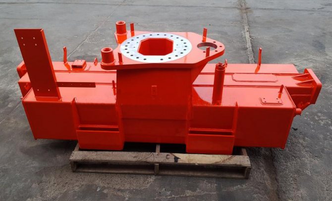
Outrigger beams are mounted into the transverse beam of the base on both sides. The base of the CMU is connected to the column structure using a supporting rotary device (SDU), which ensures rotation of the manipulator crane column.
The column rotation mechanism (rotation gearbox) is attached to the central part of the base.
The base of the CMU is mounted on the mounting installation frame of the vehicle chassis (subframe/subframe) using studs made of high-strength alloy steel.
Rotary support device (ROD)
Support-rotating devices (SPU) - with external and internal fastening, SPU fastening bolts
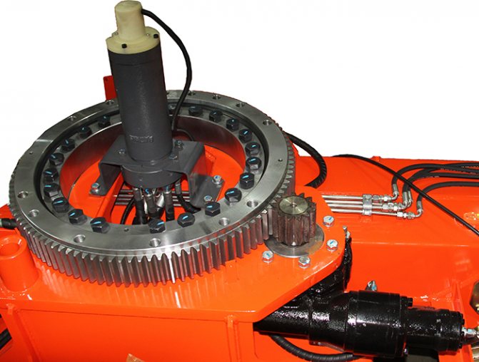
The control unit includes a rotating and a non-rotating part. The non-rotating part is bolted to the frame. The CMU column (tower) is attached to the rotating part
The rotating support device of the manipulator crane performs the function of rotating the rotating part relative to the non-rotating one.
CMU column (tower) with hydraulic collector
The column (tower) of the CMU is a closed welded structure connected to the base through the support support.
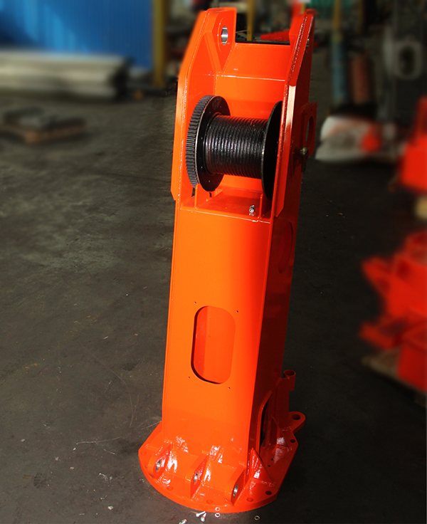
The column supports the boom using a boom lift hydraulic cylinder. A winch with a drum and a hydraulic collector are mounted in the structure of the CMU column. The hydraulic collector ensures the supply of hydraulic system oil from the stationary part of the CMU (frame) to the moving part of the CMU (column, boom, winch gearbox).
Crane boom
The boom of the manipulator crane consists of the main (fixed) boom section and retractable sections of the CMU boom (the number is from two to five).
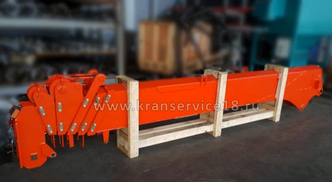
Inside the boom there are hydraulic cylinders for extending (retracting) the boom and a system of cables for extending and retracting boom sections.
Hydraulic cylinder for lifting the manipulator boom.
The CMU uses a double-acting hydraulic cylinder to lift the boom.
A double-acting hydraulic cylinder is a cylinder with a bottom welded on one side and an eye, which is attached to the CMU column.
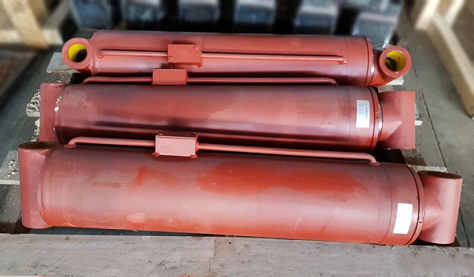
On the opposite side, the cylinder is closed with a threaded cap with a through hole for the passage of the rod.
A rod passes through the through cover, at one end of which a piston is fixed, and at the other there is a head or eye, which is attached to the boom of the CMU.
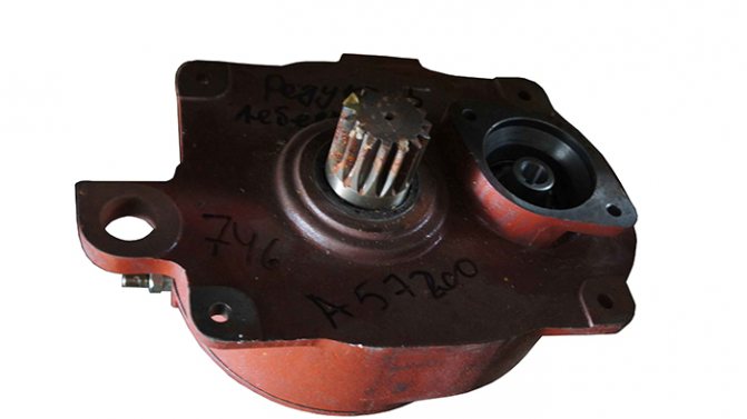
Manipulator crane rotation gearbox.
The rotation mechanism of the manipulator crane is mounted on the frame (base) of the CMU.
Consists of a rotation gearbox and a hydraulic motor. The gear shaft of the rotation gearbox rotates the control unit 360 degrees.
Winch gearbox with drum
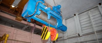
The winch of the manipulator crane consists of a gearbox with a hydraulic motor and a winch drum.
The winch is installed inside the column structure. The hydraulic brake is included in the winch gearbox.
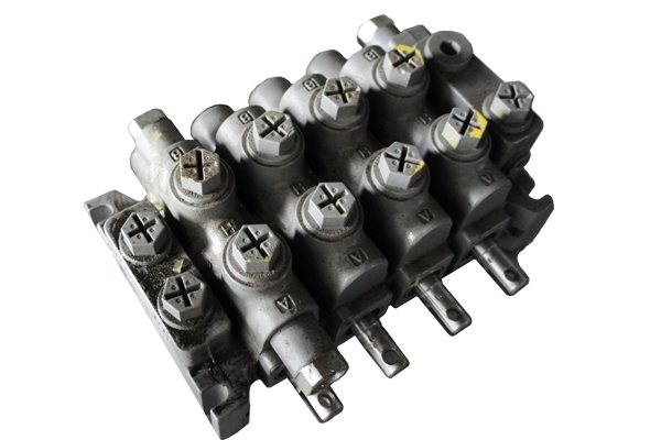
Hydraulic distributor KMU
The crane manipulator is equipped with a 6-section hydraulic distributor. Designed to control the main functions of the manipulator crane (rotation, boom lifting, extension, winch, supports). The hydraulic distributor contains a bypass valve.
Supports (outriggers) of the CMU.
The outrigger beams are welded, rectangular (polygonal) cross-section, move at the base of the CMU on supporting rollers and are fixed in their final positions by a locking device.
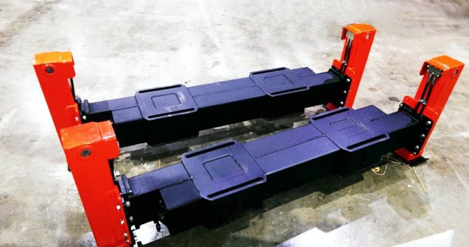
To prevent spontaneous extension of the beams, the clamps have an additional lock that prevents their opening. Mounting flanges are welded to the outer sides of the beams, to which the support cylinders are attached with bolts. A hydraulic lock installed on the rack hydraulic cylinder prevents spontaneous extension of the rack rod in the transport position and from the fall of the crane if the rack hose breaks.
Loader crane (CMU) UNIC URV504
The universally used UNIC URV504 loader crane, produced by the Japanese company Furukawa, is an excellent equipment for any type and brand of special cargo equipment serving road construction, loading, utility, unloading and other activities related to the transportation of heavy cargo. The unit operates reliably and very efficiently in a wide variety of conditions and can withstand sudden temperature changes.
Cost: on request
Technical documentation
Application/question
The rotary rotation system of this CMU makes a full rotation of 360 degrees. thanks to a hydraulic motor with built-in worm gear and self-locking brake. The design solution of the UNIC brand CMU was specially developed with the smallest number of hinge points, which gave greater rigidity to the device. As a result, the service life of the CMU has significantly increased, the time for its maintenance has decreased and the price has decreased to an acceptable level. The device is safe in operation, since it is equipped with various sensors that monitor the following values: the angle of inclination of its boom, moved weights/loads, and the length of the telescopic boom. In the event that an overload occurs that is not permissible according to the standards, the sensors block the operation of the entire CMU.
- Specifications
- Rated load
Technical characteristics of the UNIC URV504 crane
| Number of sections | 4 |
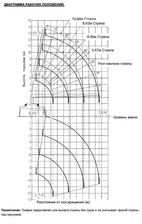
| Working radius, m | 0,67-10,6 |
| Maximum lifting capacity/at working radius | 3.030t/4.1m |
| Boom telescoping, m | 3,57-10,84 |
| Hook lifting height, m | 12,7 |
| Hook lowering below ground level, m | 12,5 |
| Boom rotation angle, degrees. | 360 |
| Width of maximally extended outriggers, m | 3,8 |
| Installation weight, kg | 1575 |
UNIC URV504 crane rated load
| Working radius, m | Lifting capacity at boom reach | |||
| 3.57m | 6.00m | 8.42m | 10.84m | |
| 2,7 | 3030 | 3030 | 3030 | |
| 3,5 | (3,33)3030 | 3030 | 3030 | 2030 |
| 4,1 | 3030 | 3030 | 2030 | |
| 4,5 | 2580 | 2580 | 2030 | |
| 5,0 | 2280 | 2280 | 1830 | |
| 5,5 | 1930 | 1930 | 1650 | |
| 6,0 | (5,76)1780 | 1730 | 1480 | |
| 6,5 | 1530 | 1330 | ||
| 7,0 | 1400 | 1230 | ||
| 7,5 | 1280 | 1150 | ||
| 8,0 | (8,18)1130 | 1080 | ||
| 9,0 | 980 | |||
| 10,0 | 850 | |||
| 10,6 | 830 | |||
The main working link of this Japanese device, of course, is the boom - profile, telescopic into four sections from 3.57 m in the initial, retracted state to 10.84 m. The hook is fixed to its head using a cable wound in four layers. This hook fastening system greatly simplifies all work with transported loads for the crane operator. The loads are dropped vertically into the precisely designated storage area. The method of pulling the cable device allows you to adjust the position of the load directly in space. At the same time, a smooth, soft lowering of it to the surface is guaranteed without jerks that are inappropriate in such a case. Consequently, the entire load is delivered undamaged, which is a significant plus for moving fragile, but at the same time large-sized materials. The maximum possible load weight is 3.030 tons, while the boom radius should not go beyond 4.1 m. The maximum attainable height for lifting the load is 12.7 m above the surface, and lowering it below the crane support is possible up to the established level of 12.5 meters. The working radius ranges from 0.67 m to 10.6 meters.
The URV504 crane-manipulator unit performs excellently when working in tandem with a powerful KAMAZ 43118 truck. The UNIC URV504 crane mounted on such a base can carry out all work related to cargo transportation without any problems or difficulties.
