Clutch device
In a MAZ car, the clutch is dry, double-disc, friction-type with cylindrical springs located along the periphery. It is installed in a cast iron crankcase. It is designed to briefly separate the engine crankshaft from the gearbox, as well as to smoothly connect them while the car is moving away and during further gear changes.
You need to know how to properly adjust the clutch, i.e. check it, lubricate the drive and release bearing following the lubrication chart. It is necessary to regularly monitor how the clutch housing mounting bolts are tightened to the flywheel housing. The tightening should be 8-10 kgm. This should be done with uniform movements, with a criss-cross sequence. After tightening the bolts, they should be secured by bending the antennae of the locking plates on the edge of the bolt heads.
Features of the double-disc clutch device
On many all-wheel drive wheeled and high-speed tracked vehicles, a friction dry double-disc, permanently closed clutch with peripherally located pressure springs is installed.
The features of such a clutch, installed on KamAZ, Ural and other vehicles, are the presence of a device (which does not require adjustment during operation) for automatically setting the middle drive disk in the middle position when the clutch is disengaged, a heat-resistant lining of the driven disk with a long service life and a certain The shape of the casing ensures fixation of the pressure springs.
The leading parts of the clutch include the flywheel 27, the middle drive disk 2, the pressure disk 4, the casing 77 with 3 bushings and bolts 19. The middle drive and pressure disks each have four pins on the pressure surface, which fit into grooves on the cylindrical surface of the flywheel and are transmitted to the drive drives torque from the engine. At the same time, the possibility of axial movement of disks 2 and 4 is provided.
The driven parts include two driven disks 7. The driven disks are steel, equipped with friction linings 22 made of asbestos composition; they are connected to their hubs through torsional vibration damper discs 24 with springs 25 and friction rings 26.
The driven disc hubs are mounted on the splines of the clutch driven shaft 23, which is also the drive shaft of the gearbox (or front gear divider).
Between the casing 17 and the pressure disk 4, pressure springs 16 with heat-insulating gaskets 18 are installed, under the action of which the driven disks are clamped between the pressure and middle driving disks and the flywheel with a total force of 10,500... 12,200 N (1050... 1220 kgf).
The clutch release device consists of release levers 6, connected at the outer ends to the pressure plate 4, and in the middle part - with support forks 5, which are installed in the casing 17, a spring 7 with a loop 9, a thrust ring 14 of the release levers and a release clutch 72 with a bearing 10, a pull-out spring 77 and a lubrication hose 8 installed on the cylindrical part of the bearing cover of the transmission drive shaft, and a release fork 75 installed on the roller 75 in the clutch housing 20.
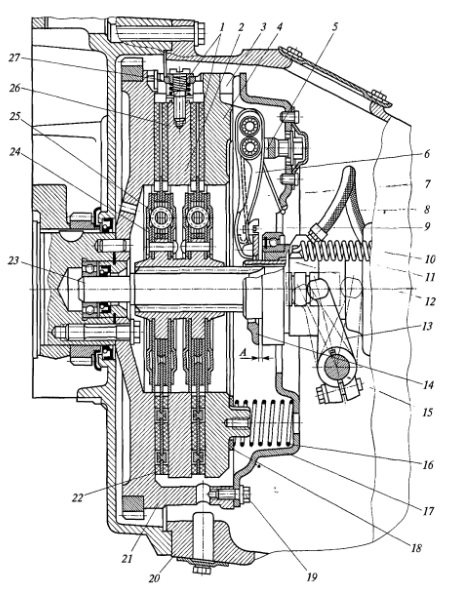
Rice. Double-disc clutch device
The middle drive disk 2 has a lever mechanism 27, which automatically sets disk 2 to the middle position when the clutch is disengaged, freeing the front driven disk 1. Thus, there are gaps between the drive and driven disks of the clutch when it is completely disengaged, which ensures clean disengagement of the clutch.
Adjustment steps
- To fully adjust the clutch, you first need to adjust how far back the middle drive plate is. This will ensure the required clearance of the clutch working surfaces. Additionally, it is necessary to adjust the gap at the end of the valve body cover and its adjusting nut, then adjust the operation of the clutch pedal.
- Next, you need to determine how to remove the middle drive disk, first removing the hatch covers from the clutch housing and flywheel. To do this, you need to engage the clutch and set the gearbox to neutral. Then you should turn the engine flywheel, while screwing the four adjusting screws into the middle drive plate all the way. First, you need to unscrew the locknuts on the screws.
- Without stopping turning the flywheel, you need to unscrew the adjustment screws one turn and secure them with locknuts. When tightening the lock nuts, you should not apply enormous force, and it is best to hold the adjusting screw to avoid shifting the adjusted gap.
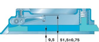
- We measure the gap between the end of the rear cover of the valve body and the adjusting nut, which should be from 3.3 mm to 3.7 mm. It is necessary to control the size of the gap after each maintenance-2. This can be adjusted by loosening the locknut and setting the required gap size. After this, you need to tighten the locknut without violating the established gap.
- The next step is how to adjust the clutch pedal. To do this, you will need a ruler, with which, after bleeding air from the pneumatic system, you will need to measure the pedal stroke. It should correspond to 34-43 mm. Free movement control should be carried out after each maintenance-1. Before doing this, you must make sure that the previously established gap is normal.
- To regulate the free travel of the pedal, it is necessary to disconnect the double-arm pedal drive lever from the valve stem fork and the clutch cylinder rod fork. At the same time, move the cylinder piston to the very bottom, and move the lower edge of the double-armed lever in the opposite direction until it stops. It is necessary to check that the holes of the cylinder rod fork and the lever are not aligned by approximately 50%. If there is a deviation upward or downward, it is necessary to bring it to the required size by rotating the cylinder rod.
- The final stage of how to adjust the clutch on a MAZ will be connecting the lever and all disconnected elements, adjusting the distance between the fork holes by rotating the forks themselves. This will be difficult to do if the friction linings of the discs are heavily worn. In this case, you will need to move the double-arm lever by 1 slot counterclockwise. Then readjust the clutch pedal travel.
Maintenance and adjustment of clutch Maz-5551, 5549, Maz-5335, 5336, 5337
Maintenance of the Maz-5551, 5549, Maz-5335, 5336, 5337 coupling consists of periodic checking and lubrication of the drive and outlet bearing in accordance with the lubrication chart. Periodically check the tightness of the bolts securing the clutch housing to the flywheel housing. The tightening torque should be 8-10 kgm. Tighten the bolts evenly, sequentially, transversely. After tightening, secure the bolts by bending the tabs of the locking plates along the edge of the bolt head.
Adjusting the clutch drive MAZ-5551, 5549, MAZ-5335, 5336, 5337
During operation of Maz-5551, 5549, Maz-5335, 5336, 5337 and its drive, the following clutch adjustments are provided:
When adjusting the amount of waste of the middle drive plate (basket) of the Maz-5551, 5549, Maz-5335, 5336, 5337 clutches, it is necessary:
Rice. 55. Clutch Maz-5551, 5549, Maz-5335, 5336, 5337 1. compression spring; 2. lock nut; 3. adjusting screw; 4. traction lever; 5. traction lever fork; 6. adjusting nut; 7. washing machine; 8. base plate; 9. main plate fastening bolt; 10. pull spring lever; 11. clutch for disengaging the clutch with the bearing; 12. lubrication hose and coupling; 13. clutch fork coupling; 14. stable ring of traction arms; 15. clutch fork shaft; 16. fork shaft lever; 17. finger; 18. clutch housing hatch cover; 19. clutch cover; 20. pressure spring; 21. thermal insulation pad of the spring; 22. pressure plate; 23. flywheel housing hatch cover; 24. flywheel; 25.
Drive discs; 26. middle conductive disk; 27. stable pin; 28. torsion disc torsional vibration damper; 29. friction of the damping ring; 30. damping spring; A. minimum clutch travel.
This Maz-5551, 5549, Maz-5335, 5336, 5337 clutch basket adjustment creates a 1mm gap between the adjusting screws and the middle drive plate, which ensures guaranteed clearance between the driven plates and the friction surfaces of the flywheel, middle plate and pressure plates when the clutch is disengaged . The clearance between the end of the valve body rear cover and the adjusting nut should be 3.50.2mm (See Fig. 56). Check this gap through one TO-2. To adjust this gap, loosen the lock nut, use the adjusting nut 18 to set the specified gap and tighten the lock nut.
Rice. 56. Clutch drive Maz-5551, 5549, Maz-5335, 5336, 5337
1. roller; 2, 11, 20, 25. forks; 3, 13, 24. nuts; 4, 7, 14. thrust; 5. pedal; 6. intermediate two-handed lever; 8. spring rod; 9. rear bracket; 10 and 12. levers; 15 and 16. hoses; 17. clutch valve; 18. adjusting nut; 19. drain; 21. two-arm clutch release lever; 22. roller; 23. bolt; 26. rod of the clutch booster working cylinder; 27. Clutch booster slave cylinder.
The free play of the clutch pedal, which should be 34-43 mm, is checked with a ruler while pumping air from the pneumatic system (with each TO-1). Before adjusting the clutch pedal free play, make sure that the gap between the valve body rear cover and the adjusting nut is within 3.50.2 mm.
To adjust the clutch pedal, play Maz-5551, 5549, Maz-5335, 5336, 5337 for free in the following order:
Repair of couplings Maz-5551, 5549, Maz-5335, 5336, 5337
When repairing the clutch, first remove the gearbox. To replace and repair drive disks or other clutch parts Maz-5551, 5549, Maz-5335, 5336, 5337, it is necessary to gradually unscrew the bolts securing the pressure disk with the clutch cover block to the flywheel, carefully remove the pressure disk, then the drive and middle drive wheels; Unscrew the four adjustment screws from the pressure plate along with the housing. The clutch pressure plate-basket Maz-5551, 5549, Maz-5335, 5336, 5337, assembled with a casing, is dismantled only if individual parts need replacement or repair. It is recommended to remove the pressure plate in the tool (Fig. 58) or on a stand for a hand press. By pressing on the end surface of the housing, the compression springs are compressed so that the release springs with the thrust ring are unloaded. Then the adjusting nuts of the traction arms are unscrewed, having first removed the support plates and lock washers. Slowly lower the press and release the pressure plate. Clutch discs Maz-5551, 5549, Maz-5335, 5336, 5337 cannot be disassembled. If it is necessary to replace the pads (for example, a gap in the pads or increased wear when the distance from the friction surface to the rivet head is less than 0.1 mm), it is necessary to replace both pads at the same time. Because even a small difference in the thickness of the pads disrupts the normal operation of the clutch.
Rice. 58. Device for assembling the clutch basket pressure plate Maz-5551, 5549, Maz-5335, 5336, 5337 with a housing
1. caliper mounting; 2. guide pin; 3. coupling housing mounting bolt; 4. mandrel for adjusting the position of the release levers; 5. bolt mounting mandrel; 6. stable cracker; 7. crackers for fastening screws; 8. clutch release lever; 9. adjusting nut; 10. lock washer; 11. Clutch pressure plate with body. The rivet heads should be placed alternately on each side of the disc. The distance from the surface of the patch to the head of the rivet must be at least 1.2 mm. The thickness of clutch discs Maz-5551, 5549, Maz-5335, 5336, 5337 with rivets of new pads should be 9.9-10.1 mm; the difference in the thickness of one disc with linings should not exceed 0.1 mm. After replacing the linings, check the driven disk for friction relative to the tire axis of the hub hole. When checking the arbor spindle, you can use the drive shaft. When inspecting the splined frame, the mileage of the friction surfaces of the disc relative to the hub keyhole is no more than 0.5 mm. Assembling the clutch cover with clutch basket Maz-5551, 5549, Maz-5335, 5336, 5337 is performed in the reverse order using a manual pressure device. In this case, install the pressure plate on the mounting stand with the working surface facing down, making sure that the tenons are locked into the grooves of the stand. Assemble the assembled traction arms with needle bearings in the grooves of the Maz-5551, 5549, Maz-5335, 5336, 5337 outlets of the clutch pressure plate and fix their axis. The needles (20 needles in each hole) must be installed on the oil. Place the thrust ring springs on the fork axle and the loops on their ends. Install lock washers on the axles of the arms and forks, then bend the middle of the washer bridge. Before installing the compression springs, install washers with heat-insulating gaskets under them. After this assembly, you can install the clutch cover on each clutch pressure head (basket) of the Maz-5551, 5549, Maz-5335, 5336, 5337 clutches, making sure that the forks of the connecting rods of the levers extend freely into the four holes in the casing. Then secure the cover to the stand using the bolts and remove it from the press. Tighten the adjusting nuts on the threaded ends of the forks, install mandrel 4 (see Fig. 58) to adjust
position of the exhaust levers to 58 ± 0.5 and secure with a bolt. All pull arms must simultaneously contact the crackers, which in turn must be flush with the top surface of the mandrel. This position provides a reference size between the working surfaces of the Maz-5551, 5549, Maz-5335, 5336, 5337 clutch basket and the traction ring, equal to 58 ± 0.5 mm. Install lock washers and backing plates onto the adjusting nuts and tighten them with bolts until the exhaust arm forks have no noticeable axial play. Bend the cored washers in the holes of the clutch housing and coil with a pattern of eight of all eight pairs of wire on one side. Install the thrust ring onto the lever rods and secure it with hinges so that it touches the supporting surfaces of all four levers at the same time. Correct installation of the ring is checked by the distance of its end relative to the working surface of the pressure plate, which should not exceed 0.4 mm with a radius of 45 mm. After assembling the Maz-5551, 5549, Maz-5335, 5336, 5337 clutch pressure plate with the casing, if necessary, perform statistical balancing with an accuracy of up to 50 Gcm. In this case, the pressure plate assembly is mounted along the central hole with a diameter of 215 mm, and the housing. through two holes. To eliminate imbalance, it is allowed to drill holes in the disk with a diameter of 14 mm and a depth of 18 mm at a distance between centers of at least 20 mm. When reinstalled into the control device, an imbalance of no more than 450 g/m2 is allowed. The repaired coupling Maz-5551, 5549, Maz-5335, 5336, 5337 is installed on the engine in the following sequence. First of all, make sure that there is oil in the crankshaft cavity under the front transmission drive shaft bearing. Then install the clutch disc so that the extended part of the hub and the head of the bolts securing the damper disc springs are directed towards the flywheel. Next, install the middle drive plate by first placing the compression springs in the four holes. The disc must move freely along the grooves of the flywheel. Then install the clamping device with cover by screwing the clutch cover onto the engine flywheel without tightening the bolts. Center the Maz-5551, 5549, Maz-5335, 5336, 5337 clutch plates relative to the engine crankshaft. To do this, insert the mandrel into the hole for the drive tire so that its end fits into the ball bearing of the crankshaft. If there is no mandrel, you can use the drive shaft of the gearbox gearbox. Next, tighten the bolts holding the clutch cover to the engine flywheel until it fails and remove the mandrel. Tighten the bolts evenly and alternately in a crisscross pattern and in two to three increments. Then install the gearbox and check that the clutch pedal does not operate as described above.
- Truck cranes and cranes
- Maz-5551, 5549, 5335, 5336, 5337 power steering
- Front axle belts and ties Maz-5551, 5549, 5335, 5336, 5337
- Clutch adjustment Maz-5551, 5549, 5335, 5336, 5337
- Regulation and repair of checkpoints “Maz-5551”, “5549”, “5335”, “5336”, “5337”
- Repair and maintenance of the rear axle MAZ-5551, 5549, 5335, 5336, 5337
- Details of the front axle and connecting rods MAZ-5516, 5440
- Steering Maz-5516, 5440
- Details of driving axles Maz-5516, 5440
Clutch care and adjustment for cars MA3-5335, MAZ 5549, MAZ-5429, MA3-5430, MAZ-504V
Clutch maintenance consists of periodically checking the clutch, washing the cylinder rod filter, lubricating the drive and release bearing in accordance with the lubrication chart (see Table 10, pp. 209-231).
Periodically you need to monitor the tightening of the bolts securing the clutch housing to the flywheel housing.
The bolts must be tightened evenly, sequentially, crosswise. After tightening, the bolts must be locked by bending the antennae of the locking plates on the edge of the bolt heads. In cold weather (below OS), it is necessary to periodically drain the condensate from the clutch booster cylinder by unscrewing the cylinder hose nut.
Before adjusting the clutch drive, you must make sure that the clutch itself is adjusted in accordance with the instructions in the operating instructions for the YaMZ-236 and YaMZ-238 engines.
In operation, there are two types of clutch drive adjustment:
1) adjusting the gap between the end of the valve body cover and the adjusting nut 18 (see Fig. 15);
2) adjusting the clutch pedal free play.
The gap between the end of the valve body rear cover and the adjusting nut should be 3.5 ± 0.2 mm. If it is necessary to adjust this gap, you need to loosen the lock nut, use the adjusting nut 18 to set the specified gap and tighten the lock nut.
Checking the free play of the clutch pedal, which should be within 34-43 mm, is done using a ruler with the air from the tractor pneumatic system deflated and the cab lowered.
Before you begin adjusting the free play of the clutch pedal, you must make sure that the gap between the rear cover of the valve body and the adjusting nut is within 3.5 ± 0.2 mm.
Adjustment of the clutch pedal free play must be done in the following sequence:
1. Disconnect lever 21 (Fig. 15) from valve stem fork 20 and cylinder rod fork 25.
2. Move the cylinder piston to its lowest position
3. Pull the lower end of the lever 21 back until it stops. In this case, the misalignment of the holes of the cylinder rod fork and the lever should be no more than the diameter of the hole for the pin, and the misalignment of the holes of the valve rod fork and the lower arm of the lever should be half the diameter of the hole for the pin. If the holes misalign by a greater or lesser amount, it is necessary to rotate the rod 26 in the fork and the fork 20 on the valve stem to bring the misalignment of the holes to the specified value.
4. Move the lever away from the stop and connect it to the valve stem fork.
5. Connect the cylinder rod fork to the upper arm of the lever.
After this, check the free play of the pedal. If it exceeds 43 mm or less than 34 mm, it is necessary to additionally adjust the free play in the above sequence.
If, as the friction linings of the driven clutch discs wear out, it is possible to reduce the distance between the forks
11 and 20 and the shortening of the cylinder rod 26 will be exhausted, you should remove the lever 21 from the clutch release fork shaft, move it one slot counterclockwise and make adjustments in the order described above.
content .. 71 72 76 ..