Specifications
Construction lifts or façade cradles are used to equip the façade. This device is used to transport workers, machinery, and building materials along the outer wall of a multi-story building. The cradle can only be installed if the façade of the building does not have protruding elements. The lifts are equipped with safety equipment for working at heights.
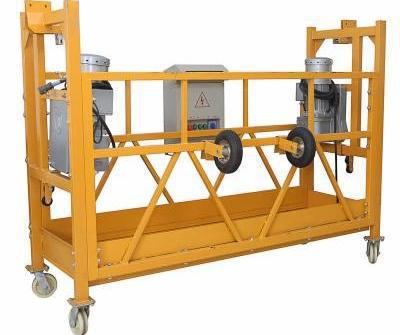
Lifts vary in technical parameters. The main indicator on which work productivity depends is the maximum load weight. For a facade lift, this figure ranges from 350 to 550 kg. The ZLP 630 cradle is made in the form of a metal platform with a fence 1.5-2 m high. The lifting occurs on 2 ropes, which are located on the sides of the cradle. The reach of the console should determine the free movement of the platform along the wall.
There are counterweights on the roof, the mass of which depends on the size of the platform and load capacity. The movement of the structure is carried out through the operation of an electromagnetic motor and a winch. The motor power is selected depending on the load capacity of the cradle.
A standard construction facade lift is designed to lift 1-3 workers. The lifting height of the cradle ranges from 2 to 200 m. The lifting speed is regulated by the gearbox. The speed ranges from 5 to 10 m/s. To ensure safe work, 2 safety cables and a catcher are installed, which is an insulated block that stops the winch when the cable breaks or the cradle tilts.
Disc brakes ensure the platform quickly stops when overloaded. The lift is supported on two beams or consoles mounted on 4 cables. 2 main cables, and 2 safety cables. 2 drums are installed under the platform, and a winch moves along them. New designs are provided with a power source, which ensures autonomy of operation at height.
Carrycot ZLP 630
If you are faced with the task of purchasing equipment for working on building facades, pay attention to the ZLP 630 facade lift. This is the most popular and in demand model, which is used when performing various construction and repair work of any level of complexity.
Attached to the roof of a building, such a mechanism does not require a level base for installation, unlike the same scaffolding.
Design features and advantages of the model
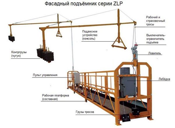
The components of this facade lift include a working platform, consoles, counterweights, suspension and safety ropes, an electric motor and a control unit. The working platform consists of three sections, two meters long. Thanks to this, the dimensions of the lift can be changed depending on the work being carried out. So the length of the working platform can reach up to six meters. For safety reasons, additional modules cannot be used or this maximum length can be increased.
Retractable consoles included in the structure make it possible to carry out work on buildings with various architectural projections and balconies. The ZLP 630 is a practical platform that is suitable for a wide range of jobs and is more practical and manoeuvrable than conventional scaffolding. The mechanism is capable of lifting up to 630 kilograms of cargo; 4 people can work simultaneously on an area of six meters. If necessary, you can mount a platform two or four meters long.
Application
The ZLP 630 model cradle is so versatile and practical that it is used in a wide variety of areas, in particular:
- construction, repair and installation work outside buildings;
- insulation and cladding of facades;
- installation of attachments;
- cleaning and washing of windows, walls and facade glazing;
- repair and construction work on bridges, reservoirs, dams and industrial pipes;
- installation of signs, banners and outdoor advertising.
The universal construction lift model ZLP 630, capable of lifting one or several workers, is actively used in the work of organizations of various profiles. Subject to proper operation and compliance with all safety rules, the mechanism does not lose balance even at a height of 150 meters above the ground.
The unit’s safe motor does not overload the network, and special fastening systems make it possible to easily and quickly secure the cradle at the required height. Each lift of this model is equipped with an emergency braking system.
Popular models
Facade lift 3851b has the following technical characteristics:
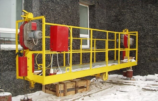
- load capacity - 300 kg;
- platform length - 6 m;
- maximum lifting height - 150 m;
- consoles have lengths of 0.9 m, 1.5 m and 2.5 m.
Lifts 3851-B with a non-demountable frame are used for work at heights, for lifting workers and loads during the repair and construction of buildings. The façade lift kit includes LEF-500 winches, catchers and spare parts. The lifting speed is 9.7 m/min. Electric motor power - 1.1 kW. The dimensions of the working platform are 5.4x0.86x1.01 m.
Advantages and disadvantages of the cradle LE-6-100-300
Now let’s look at the “classic” – the 6-meter construction cradle LE-6-100-300. The name of the LE model stands for “electric cradle”. The number 6 indicates the length of the working platform in meters, the number 100 indicates the maximum lifting height in meters, and the number 300 indicates the load capacity in kilograms. This model is produced by a number of Russian, Belarusian and Ukrainian factories and can also be labeled as PF (facade lift), as well as LEU (universal) and LES (construction).
Gearbox
On this topic
15510
Combat icebreakers - myths and reality
NATO admirals are concerned about the lack of such ships in the alliance
The cradle LE-6-100-300 is equipped with a friction-drum winch with an electric drive of 0.75 kW. Its main advantage is good maintainability, thanks to a large number of new and used spare parts. In addition, most craftsmen are familiar with the peculiarities of their repair.
There are many more disadvantages: - complexity of packing the cable; — frequent breakdowns of the solenoid coil in gearboxes with drum brakes, as well as the need to adjust the brakes. The best solution to this problem is to install a drive with a built-in electromagnetic brake, but its cost is twice as high. It is much more reliable and rarely breaks, but if it breaks, it is much more difficult to repair by ordinary craftsmen.
Working platform
The working platform of the LE is most often non-demountable, 800 mm or 900 mm wide. Its advantages are a rather thick metal profile and the presence of an entrance.
The shortcomings include the not very durable perforated platforms, which quickly sag and therefore require reinforcement with steel plates. Wheel supports also fail quickly.
Consoles
In these cradles, two types of prefabricated consoles are installed - arched or tubular, both 8 m long. They have identical technical characteristics, except for weight. The assembled tubular console weighs 250 kg, and the arched console weighs 165 kg.
Advantages: large reach of consoles (up to 2.5 m); collapsible design, consisting of 4 parts, facilitates installation and transportation; Possibility of installation on the corner of a building.
Disadvantages: the arched console can be damaged in cold weather due to water entering the cavities, and its assembly is often carried out using a sledgehammer, which also often causes damage; Console parts do not always fit well and have to be adjusted the first time they are used.
Installation
Installation and assembly of the façade lift is carried out according to the rules. Workers installing the roof console must exercise caution. When working on the roof, you must be secured with a rope. To install the cradle, you need to check the strength of the connections of the nodes; all fasteners must be securely tightened.
You also need to make sure that there is lubrication in the winches, rollers, and blocks. The cradle must have 2 manual drive handles. There must be the necessary supply of ropes. The consoles must be positioned so that the beams are in a horizontal position, the distance between the console axes is 4200 mm and the console overhang is 550 mm from the wall to the rope axis.
After being attached to the consoles, the lifting ropes are threaded into the winch drums and pulled to the ground with a load weighing 20 kg. Then the cradle is installed, connected to the power supply and checked for readiness for use. You can connect the cable to the power source at the bottom or in the middle of the house. When the cable comes out of the window, you need to put a support so that the cable does not break. If the cable length is more than 30 m, it is suspended from the platform with a steel cable.
After suspending the platform, you need to check the electric drive lock, raise the cradle 200-300 mm from the ground and check the stability of the consoles. Check that the lift height limiters are securely installed. Check the operation of the adjustment buttons and systems that eliminate misalignment. Check the operation of mechanisms and brakes. Assembly takes place with the participation of workers who will work on the lift and under the supervision of the foreman.
How is a façade lift installed?
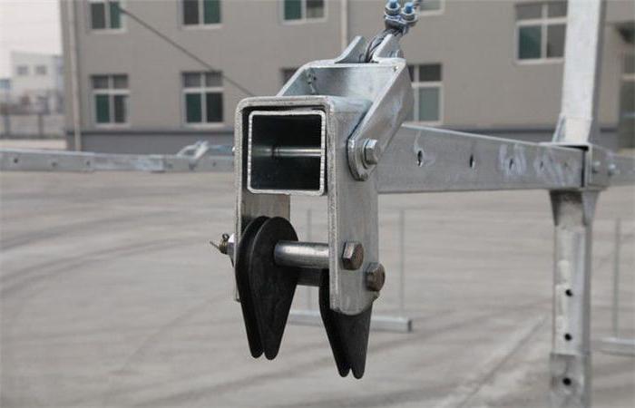
Installation begins with the assembly of the platform base. The cradle platform is based on load-bearing T-shaped supports - rear and front. Each support is formed by two metal parts that strengthen the structure. Typically, T-profiles allow the frame to adjust the lift in height and sometimes in width. Assembly of side and adjacent profiles is carried out using bolts, clamps and brackets. At the final stage, the equipment for attaching the cable is installed.
Various devices can be used for this. For example, the ZLP façade cradle lift provides for the fixation of rollers, on which the cable is subsequently attached, which in turn is installed on the roofing supports of the roof.
Lift test
Testing of facade lifts begins with checking the functionality of the system. First, static tests of the lift are carried out. To do this, raise the apparatus to a height of 150 mm. A test weight weighing 1260 kg must be placed on the platform flooring, distributed over the entire area, and held in this position for 10 minutes. This is how they check the reliability of the brakes that should hold the cradle. The platform should not lower itself. Then you need to put the device on the ground. Check for any deformation of the mechanisms.
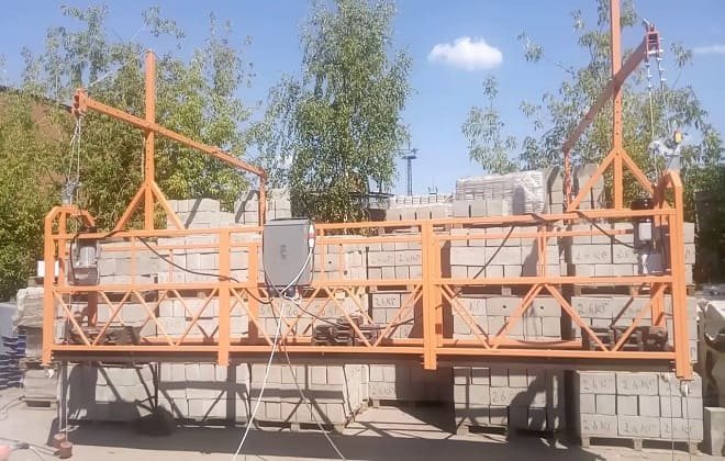
Then the lift is dynamically tested. A counterweight weighing 693 kg is placed on the floor with a console overhang of 1.05 m. The remote control is turned on. The device is raised and lowered five times to a height of 3 m, making 3 stops. The cradle should stop immediately when you press the up or down buttons.
Spontaneous lowering of the platform is unacceptable. Then the brakes are tested. Having installed the load, raise the cradle to a height of 500 mm. Raise the brake handle of the left winch up. The platform will gradually descend on the left side. Release the handle. Then the downward movement should stop. Then do the same to test the right winch.
Purpose of façade lifts
Construction cradles are suspended equipment necessary for a wide variety of work.
They are used at altitudes up to 150 meters and are used for:
- external construction work;
- repair, cleaning and maintenance of high-rise buildings;
- installation of large equipment;
- construction and maintenance of reservoir dams and hydroelectric dams;
- construction and repair of bridges;
- chimney repair;
- decorative finishing;
- painting;
- window installation;
- installation of elevators;
- welding of ship hulls.
Where to buy a facade lift
A wide range of models with different technical characteristics is offered by Vse-podemniki.
All items in the catalog meet modern quality standards and safety requirements. The company cooperates with manufacturers directly. You can buy certified equipment with a quality guarantee at a competitive price. Vse-podemniki consultants will help you choose the optimal models, taking into account the specifics of the client’s work.
You can order a lift on the company’s website. Flexible pricing policy, prompt delivery to all regions of the Russian Federation, full information and service support for customers - in Vse-podemniki you will find a reliable partner for many years.
Construction cradle facade lift
EXTRACT FROM OPERATING INSTRUCTIONS lifting equipment - facade lifts, construction cradles ZLP1. Description: facade lifts, construction cradles Suspended machinery is multi-purpose and very effective, used for work at heights of up to 150 meters. Facade lifts construction cradles are used for work on wall structures, decorative finishing, painting, window installation, cleaning and maintenance of high-rise buildings, etc. Construction cradles can also be used for constructing elevators, welding ship hulls, and working on chimneys, bridges and dams. This equipment is manufactured in accordance with the national standard GB 19155-2003. Facade lifts and construction cradles are easy to use and store. 3. Facade lifts, construction cradles - control principles and technical features. The equipment of construction cradles consists of lifting winches (gearboxes), a lifting platform, catchers, working and safety cables, a suspension device (consoles) with counterweights (counterweights), and an electrical control system. 3.1 Hanging mechanism of the construction cradle (console) 3.1.1 The hanging mechanism includes front, middle and rear beam, front seat, rear seat, upper column, counterweight, reinforced rope, gate, etc. To comply with the operating modes of the front and rear beams, the height of the lifting mechanism can be adjusted within certain limits. In addition, the hanging mechanism can move on rollers on the base. 3.1.2 The configuration of the suspension mechanism should correspond to the following equation: K=G×b/(F×a)>2 K——- rollover protection coefficient G———weight of counterweight and rear seat (kg) a———length of front seat beam (m) F——-total weight of platform, lifts, electrical system, safety lock, cable and rated load, plus wind pressure (kg) b——distance between front seat and rear seat (m) If length (a) of front beam 1.5 m or more on a suspended platform, the load weight should be reduced. 3.2 Lifting platform of the ZLP construction cradle lift 3.2.1 The frame of the lifting platforms is made of profiled steel pipes. The parts are secured with bolts and nuts. The length of the standard section is 2.5 or 2 meters. The height of the balustrade on the working side is 970 mm, on the outer side 1120 mm. The coating of the construction cradles platform is anti-slip. The construction cradle platform is equipped with 4 swivel wheels, which makes it possible to move the platform when lowered to the ground. 3.3 ZLP Construction Cradle Hoist Lifting Device 3.3.1 ZLP800 Construction Cradle Hoists include electromagnetic brake motor, centrifugal speed limiter, twin brake system, wire tension system. The construction cradles lift uses a slider lifting mechanism of the “S” type. 3.3.2 Lifting mechanisms (winches) in construction are equipped with an electromagnetic and centrifugal brake. The winches have an “alpha” type lifting mechanism. 3.3.3 The hoist rope is loaded into the winch automatically. To do this, you need to insert the lower end of the rope into the hole in the lifting mechanism and turn on the winch to lift. ATTENTION! The end of the cable must be sealed! 3.3.4 The electromagnetic brake of the construction cradle lift drive is self-adjusting to create a braking torque to stop and hold the suspended platform. In the event of a power failure or accident, the fork of the manual lowering unit (inside the lift handle) can be connected to the electromagnetic brake through a hole in its fork (under the motor housing) to lift the fork and release the brake so that the suspended platform slides down at a uniform speed. 3.3.5 The construction cradle lift is cooled by transmission oil, which must be changed periodically every 6~12 months depending on operating conditions. Recommended gear oil No. 18 with double characteristic curve, lifter capacity 1.2 liters in ZLP800 to 2 liters in ZLP630 or ZLP500. At extremely low temperatures, universal gear oil No. 80W90 is recommended. 3.4 Safety interlock. Safety of the construction façade cradle ZLP Safety locking of the construction cradle is a separate mechanical block that automatically blocks the cable when it breaks or the suspended platform of the construction cradle is tilted to the limit. There are two types of safety interlock. Test safety interlock or centrifugal speed limit safety interlock is applied according to different shapes of suspended platform. 3.4.1 The rollover safety lock includes a cable clamp, a coupling plate, a torsion spring, a bracket, a swing arm and a roller. They are arranged in such a way that the operating cable is tensioned by a roller on the swing arm, the cable clamp opens and freely passes the safety cable. If the suspended platform of the construction cradle lift is tilted to the limit or the work cable breaks, the pressure on the swing arm of the safety lock is reduced. The clamp grips the safety cable and prevents the suspended platform from falling or tipping over due to friction between the torsion spring, the clip and the cable. If the rollover safety lock is used, the inclination angle of the suspended platform of the construction cradle should be 3~8 degrees. The ZLP800, ZLP630 and ZLP500 construction cradle lift models are equipped with two tip-over safety locks. 3.4.2 If the lowering speed of the suspended platform of the construction cradle lift exceeds the limit (22 m/min), the centrifugal speed limiter cam starts the clamping device and the safety rope is locked within a distance of 20 cm, stopping the platform. (This type of safety locking is used on equipment with one hanging point (cradle construction models ZLP-250)). 3.4.3 The safety interlock has the original factory markings. As labeled, a professional technician will perform the service at 12-month intervals and note the end of 12 months (if the safety interlock is operated in dusty, corrosive or adhesive environments, the repair and service interval will be reduced to 6 months). 3.5 Construction cradles lifts . Electrical control system
3.5.1 Power supply for construction cradles Power supply via a 3-phase 5-wire system via a 5-core 2.5 mm2 cable via power socket Q1 to the control cabinet via a 3-phase leakage breaker. X1, X2 and X3 are 3-phase power lines, PE is the ground line. Users should connect using a 3-phase 5-wire system. 3.5.2 Emergency braking, overload protection circuit for construction cradles The motor is powered through a common contactor KM1, motor control contactors KM2, KM3, KM4, KM5, thermal relay FR1, FR2 and motor sockets Q3 and Q4. In case of an unusual situation, emergency braking for the safety of the construction cradle can be performed by pressing the emergency brake switch on the electrical control cabinet panel to turn off the general contactor KM1, the motor power is turned off and the hoist stops. Thermal relays are capable of turning off the power automatically when the motor is overloaded. 3.5.3 Braking diagram of the construction cradle lift motor. The construction cradle motor brake is mounted under the motor casing and the voltage is rectified to 99 VDC for 220 V single phase AC (108 VDC for 240 V single phase AC) through a half wave rectifier module. The brake rectifier module is installed inside the electrical control cabinet. 3.5.4 Control circuit for construction cradles The control circuit for the construction cradles is powered by a current of 36 V or 24 V from the control transformer T, which can be easily adjusted in the electrical control cabinet and with a manual switch. The engines can operate simultaneously and independently by turning the switch on the control cabinet panel. When the switch is turned to one side, one motor of the construction cradle runs. 3.5.5 Top limit switch and alarm circuit The top limit switch is installed on the upper working section of the suspended platform. When the motion switch turns on the limit switch, the engine stops and the alarm sounds. 3.5.5 To facilitate operation, terminals N1 and X11 in the electrical control cabinet are used to power lighting and hand tools. However, you cannot use high-power tools, for example, welding machines, iodine lamps, so as not to damage the circuit and elements. 3.6 Working cables of the construction cradle lift 3.6.1 The cable in the lifts is specially galvanized. The construction cradles of the ZLP800 model use a cable made of steel cores of the 6×19W+IWS design, with a diameter of 8.3 mm, a nominal strength of 1960 MPa, a breaking force (the greater is equal to) 64k N. The cable in the ZLP630 or ZLP500 construction cradles with textile cores of the 4× construction 31SW+NF, diameter 8.3 mm, nominal strength 1960 MPa, breaking force (greater equals) 64k N. 3.6.2 The end of the cable is attached according to the specification GB5144-86 (see drawing 8), a horseshoe bolt is attached to the back of the cable, The clamp secures the working part of the cable so that the cables do not get tangled. The clamp can also be located on the cable; there must be at least 3 clamps, the distance A between them is about 60 mm. The loop is tightened in the following order. The cable must have factory markings. It is prohibited to weave a cable with another cable or to extend it. 3.6.3 Maintenance and inspection of the construction cradle lift cable The cable should be properly maintained to avoid corrosion and dirt, and should be regularly checked for deformation and breaks. The cable is rejected in accordance with specification GB5972. Special Note: Cradle wire must be replaced in the following cases: a. Looseness, twisting, unwinding, other deformation or loss of integrity. b. The cable is rejected when the number of broken wires within the distance “ab” reaches 5. When rust appears or the rejection period is shortened. The reduction percentage is equal to the maximum allowable number of 5 breaks multiplied by the percentage of corrosion or abrasion on the cable surface. c. Obvious corrosion on the surface of the cable, depressions and weakening of the cable. d. The nominal diameter of the cable is reduced by 6%, even in the absence of lay fractures. e. When abrasion along the outer contour of the cable reaches 40% of the diameter. f. Damage or accumulation of defects due to heat or electrical arcing. 4. Installation of lifts and construction cradles 4.1 Preparation for installation of the front Before installation, check the completeness according to the packing list. Check the condition of parts and components.
4.2 Installation of the hanging mechanism, construction cradle console 4.2.1 Insert the knobs into the front and rear posts, respectively, and tighten the bolts. The front and rear posts consist of two parts and are height adjustable (the height is adjustable within 1.15~1.75 m according to the height of the parapet or roof slope). 4.2.2 Slide the front beam (with clamp plate) through the coupling on the front column column (the length of the front beam depends on the actual needs), put on the upper spacer post, tighten the bolts and nuts of the construction hoist. 4.2.3 Slide the middle beam onto the front beam (the length depends on the actual needs), install and tighten the bolts and nuts. 4.2.4 Slide the rear into the middle beam (the length depends on actual needs), install, tighten the bolts and nuts from one end. Insert the other end into the rear pillar coupling, insert the coupling into the two holes on the end, then install and tighten the bolts and nuts. 4.2.5 Place the open side of the screw tie on the coupling onto the rear pillar column. Insert one end of the reinforced cable (7 m long) into the front beam coupling and tighten the cable clamp (in the direction of drawing 8). Pass the reinforced cable along the pulley on the spacer post, and the other end through the hole in the blind side of the screw tie, tighten the clamp. Adjust the threaded rod of the screw tie, tension the reinforced cable to raise the front beam by about 3 cm. 4.2.6 Secure the working cable and safety cable with clamps (in the direction of drawing 8), put the stopper on the safety cable, as it may be required according to with actual conditions. 4.2.7 Place the suspension mechanism in the working position, and the working wall of the front suspension plate should be at a distance of approximately 60 cm. The distance between the two front suspension plates of the suspension mechanism should coincide with the length of the suspension platform. Hang the weights and slowly release the cable. 4.3 Installation of the suspended platform of the construction cradle 4.3.1 Lay the bottom plate of the construction cradle horizontally on the ground, install the balustrades, place the bolts and nuts in place, do not tighten them yet (see attached drawing 2). 4.3.2 Install the roller wheel to the lift mounting frame. The lift frame must fit at the ends of the suspended platform; place the bolts and nuts in place without tightening them yet 4.3.3 Check the correct assembly of these parts. 4.3.4 Tighten the bolts connecting the parapet and the bottom plate, the bolts connecting the balustrades. Tighten the bolts securing the balustrades to the lift frame. 4.4 Installation of lifts, safety interlock and electrical control cabinet on the ZLP construction platform . 4.4.1 For ZLP630 or ZLP500, mount the lifting devices on the construction cradle lift mounting frame, secure with bolts, nuts, handles and locking pins. Mount the safety lock on the lift frame bracket, install and tighten the bolts. 4.4.2 Mount and hang the electrical control cabinet in the center of the parapet of the suspended platform. 4.4.3 Insert the motor plug and the detachable plug. Set the upper limit switch to the right safety lock position. Insert the plug into the socket of the three-phase power supply system with five wires. 5. Construction cradles lifts. Operation and checks 5.1 Checks and adjustments 5.1.1 Check that the connection diagram is correct. The voltage should be within volts 380 5% (415 5%). After connecting to the network, press the leak breaker button, which should respond quickly. Close the door of the electrical control cabinet, check the normal operation of the switch and motor by turning the switch. 5.1.2 Checking and adjusting the electromagnetic brake of facade lifts The distance D between the armature and the electromagnetic disk should be within 0.5~0.6, the design is shown in Fig. 11. First loosen the internal hex screw 1 on the electromagnetic disk 2, then rotate the hollow screw 3 to adjust the distance around, finally tighten the internal hex screw 1. Turn on the power to check the operation of the electromagnetic armature, the armature should be completely separated from the friction disk when released, if not a power failure occurs. The anchor presses the elastic disk under the action of a spring. 5.1.4 After passing the cables on both sides, raise and level the suspended platform of the facade lift at a level of 1 meter above the ground. Secure a heavy load to the safety rope at a height of 15 cm above the ground. 5.1.5 Carefully collect excess parts of the cable and pack it so as not to deform it. 5.2 Test run of the construction cradle lift 5.2.1 Prepare a safety cable for independent fastening to the attachment above the work area. The operator must have a protective helmet and a safety belt in accordance with safety requirements, fasten the belt to the safety cable. 5.2.2 It is necessary to check the condition of the locking cable of facade lifts in the following order: turn the switch on the panel of the electrical control cabinet of the construction cradle to the middle position, raise the suspended platform by 1~2 cm and stop, then turn the switch in the other direction and tilt the suspended platform. When the suspended platform tilts 3~8 degrees, the safety lock will lock the safety rope. When the bottom edge of the suspended platform is raised to the leveling position, the safety lock automatically disengages and releases the safety cable. (The left and right safety locks of construction cradles should be checked in the same order). 5.2.3 Zero load test: no abnormal noise in the lifting devices of the construction cradle, normal reliable operation of the electromagnetic brake. Press the “emergency braking” button, the suspended platform should stop. 5.2.4 Manual lowering check: Pull out the fork from the lift handle and insert into the hole under the motor casing to lift, the suspended platform should move smoothly at a uniform speed not exceeding more than 1.5 times the rated speed. 5.2.5 Adjusting the upper limit stop: Raise the construction cradle to working height, adjust the upper end stop and the angle of the upper limit switch hinge arm. 5.2.6 Rated load test: The rated load for façade lifts must be distributed evenly over the working platform. There should be no abnormal noise during operation, and sliding should be smooth. The safety lock should securely lock the safety cable when the cradle platform is tilted. 5.3 Regular inspections of the mechanisms and structure of the construction cradle 5.3.1 Checking the cradle before operation: check the normal condition of the facade lift, the connection between the lift and the suspended platform, normal cable tension, absence of abrasion and tears. 5.3.2 Check with power on: check the working condition of the suspended platform of the construction cradle according to paragraphs 5.2.3, 5.2.4 and 5.2.5, the lift should not vibrate excessively, the electromagnetic brake should be elastic when braking, the safety lock should lock normally. 5.3.3 Foreign objects, for example, cement mortar, glue, waste paper and paint, should not get into the safety lock of the façade lift. After the shift, lower the suspended platform construction cradle to the ground, loosen the work cable to release the hinged safety lock lever. Turn off the power and lock the electrical control cabinet. When storing outdoors, protect the construction hoist, safety interlock and electrical control cabinet from precipitation. The cable must not be bent to prevent the ingress of grease and dust, welding stains and erosion. If defects are noticed according to paragraph 3.6.3, the cable should be replaced immediately. 6. Construction cradles lifts. Safe operation procedure 6.1 Access to and maintenance of suspended equipment is permitted only to qualified personnel with sufficient technical training. 6.2 Personnel on the construction cradle platform must have safety helmets and be fastened with a belt to the safety cable, as required by safety regulations. 6.3 The platform of the construction cradle lift must be grounded, the load must be approximately evenly distributed over the platform. Do not overload the platform or operate the platform if the lifts or safety locks are faulty. 6.4 When the platform is running normally, do not manually brake the motor or safety interlock to prevent an accident. 6.5 When operating the platform, the operator should monitor its condition and quickly identify hidden faults that could lead to a construction cradle failure. 6.6 When the limit switch is triggered, the construction cradle platform automatically stops and the buzzer sounds. In this case, quickly lower the platform to move the limit switch away from the stopper. 6.7 The platform of the construction cradle should be quickly adjusted if the side tilt or the fall height exceeds more than 15 cm. 6.8 If the power goes out during operation, first turn off the power. If it is necessary to lower the suspended platform of the façade lift to the ground, apply the method in paragraph “5.2.4 Checking manual lowering” with an electromagnetic brake so that the platform of the construction cradle smoothly lowers to the ground. 6.10 In the event of a break in the working cable during operation, personnel can calmly leave the construction cradle platform without panic, observing safety requirements. Repair and maintenance personnel arrive at the platform to replace them, prevent the load from falling and fix the platform with a safety cable clamp, securing it with a cable to the construction roof. Then a new cable is pulled through the hoist; To raise the platform, press the lifting button of the construction cradle. If the overhead equipment operates normally, carefully release the safety lock, disconnect the locking cable, and lower the platform to the ground. It will be accepted into service only after strict inspection. 6.11 The operation of the suspended equipment of the construction cradle must meet the requirements for performing high-rise work. Construction cradles cannot be used in thunderstorms, fog, or force 5 winds (wind speed 8.3 m/s or higher). 6.12 Construction cradles should be placed at a distance of 10 m from high voltage power cables. 6.13 Do not use any additional equipment, such as ladders, containers, to increase the height of the suspended platform. Do not use any attachments that exceed the permissible platform length. Materials and equipment are stored in a locked area within the platform. 6.15 The safety interlock should be checked and lubricated regularly during its service life; You cannot clear the lock without approval. Pay special attention to the service life of the safety lock on the marking. 6.16 If the construction cradle is stored outdoors, the platform, lift, safety interlock and electrical control cabinet should be protected from precipitation. 6.17 If a cable is removed from a facade lift, it should be wound into a coil and stored correctly. 6.18 Hanging equipment for construction cradles should be stored in a dry, well-ventilated area that does not contain corrosive gases. 8. Construction cradle. Care and maintenance Careful care and maintenance of the suspended equipment of the construction cradle are mandatory conditions. Strict adherence to responsibility not only allows you to keep the equipment in perfect condition, but also guarantees the safety of personnel and increases the service life of construction cradles. Regular maintenance of facade lifts includes compliance with regulations, regular inspections and repairs. Regular maintenance and inspections before and after operation of the façade lift must be carried out by the operator, and regular inspections and repairs must be carried out by qualified personnel. 8.2 Regular inspections: Every day before work, the operator must check the construction cradle in accordance with paragraph 5.3, especially the safety lock, hoist and cable. 8.3 Regular inspection of the construction cradle: the user must develop clear rules in accordance with the operating conditions and time (generally 1~2 months), after the end of the period, the entire construction facade lift machine should be inspected. Qualified personnel should check for wear of parts, replace fragile and defective parts, and disassemble for cleaning and changing grease and oils. You should check the condition of the electrical control cabinet circuit and the absence of leaks in the entire machine. If the user follows the rules of care, operation and maintenance, major repairs of the construction facade lift are required once a year. When working in dusty conditions or with corrosive materials, the repair cycle is correspondingly reduced. 8.4 The cycle on the safety lock marking is 12 months after shipment of the façade lift. After this cycle, the user must submit a request to the distributor or manufacturer for service by specialists. (The specified safety locking cycle for construction cradles is reduced when used in dusty, corrosive or sticky environments.) The cable is discarded as indicated above in accordance with the rejection standards. 9. Handling and storage of construction cradle Construction cradle lifts should be stored in a dry, well-ventilated area without corrosive gases. If façade lifts have been in storage for more than a year, re-service should be performed.
Product design
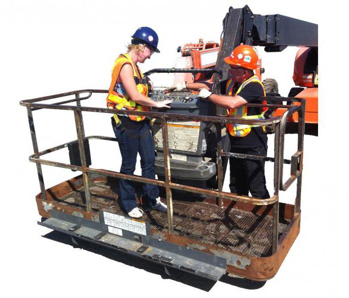
So, the facade lift has the following structure:
1. The platform on which the person will actually stand. In another way it is called a cradle.
2. Consoles on the roof of the structure, with the help of which the platform will be suspended.
3. Cables or ropes, the length of which is at least 100 meters.
4. Counterweights, the mass of which should be about 25 kg.
5. Belay catchers.
Naturally, such a product must have a control panel with which you can adjust the height and position of the platform. That is, the ZLP facade lift has a simple and understandable device.
Advantages
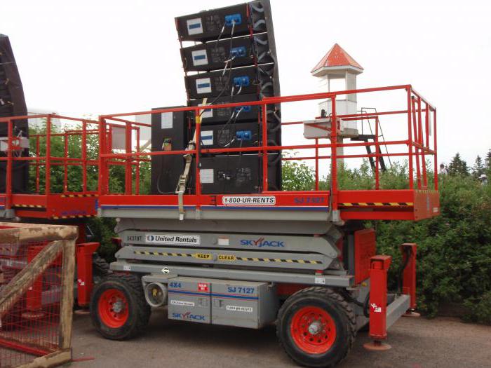
Among the advantages of the device are the following:
— Ability to perform work of any complexity.
— Repeated use, and, therefore, long service life.
— Multifunctionality.
— Acceptable cost.
— Large safety margin.
— Various device sizes.
— Easy to transport and use.
As you can see, a facade lift is indispensable for high-rise work.
Areas of application
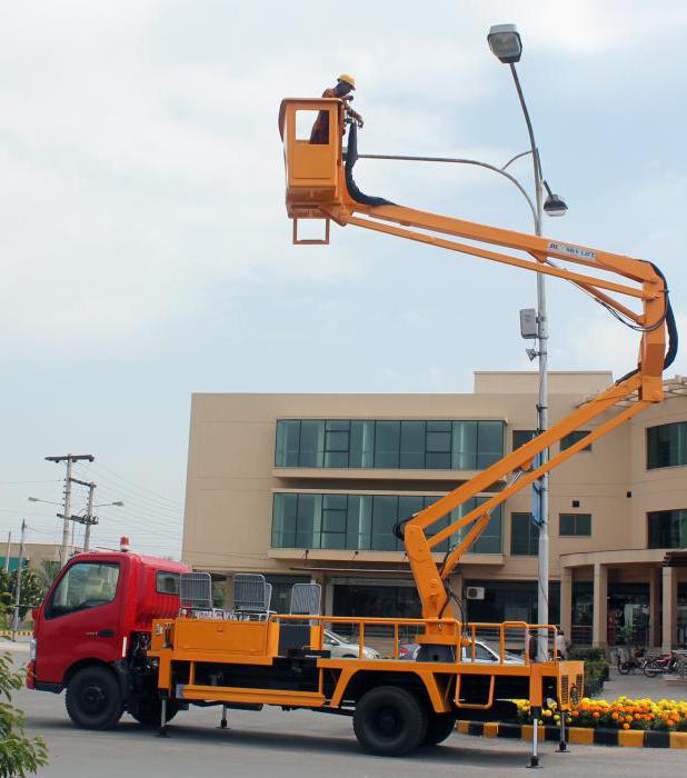
The presented product is intended mainly for performing repair or cleaning work at high altitudes. This platform can accommodate one or two people. It has a rather complex device. In addition, it has some technical requirements. Be sure to do so while working.
Most often, facade lifts are used in construction. Thanks to it, you can not only carry out repair work, but also transport building materials upstairs. Workers can be delivered to the site in the same way. The device is also used for welding work on bridges, ships, dams and other structures for the repair of which standard methods cannot be used.
Lift operation
By the time of the first test, the electrical wiring and functionality of the control panel must be checked. A safety cable is also prepared. It must have independent fixation above the work area. In accordance with safety regulations, workers and operators must wear helmets in the work area. Then you can begin the lifting process. The operator selects low speed when starting the lifting mechanism. Then it can be gradually increased, but in accordance with regulatory limits - up to 10 m/min. When the façade lift reaches the desired level, the operator stops the drive and sets the safety cable lock to active mode. From this point on, workers can begin installation and repair operations in the target area.
