Adjusting the thermal clearances of the engine valves of the GAZ-66 and GAZ-53 cars
Remove the valve covers.
We turn out the spark plugs.
We set the piston of the first cylinder to top dead center; to do this, close the hole for the spark plug of the first cylinder with your finger and turn the engine crankshaft with the starting handle until air begins to escape from under the finger. This will happen at the beginning of the compression stroke in the first cylinder.
| Rice. 1 |
Having made sure that compression has begun, carefully turn the engine crankshaft with the starting handle until the pointer on the clutch housing coincides with the ball cased into the flywheel (Figure 1), and for the GAZ-53 car - until the marks on the crankshaft pulley coincide with the central mark of the pointer c. m, t. (Fig. 2).
| Rice. 2 |
When the piston of the first cylinder is at TDC on the compression stroke, the intake and exhaust valves must be completely closed.
| Rice. 5 |
In this position, we install or check the gap between the rocker arm and the valve stem, which should be 0.25 - 030 mm on a cold (15 - 20 ˚ C) engine.
| Rice. 3 |
It is allowed to reduce the gap to 0.15-0.20 mm for valves located at the edges of the heads: the first and eighth inlet, the fourth and fifth exhaust (Fig. 3).
If the gap does not match: - loosen the lock nut of the adjusting bolt and, by rotating the adjusting bolt, set the required gap on the feeler gauge. Tighten the locknut, holding the bolt from turning, and check the clearance again.
We adjust the clearances of the remaining cylinders in the order of operation of the cylinders 1-5-4-2-6-3-7-8, turning the crankshaft by ¼ turn when moving from cylinder to cylinder.
| Rice. 6 |
To better navigate and speed up the process, use quick-drying paint to mark the drive pulley into four parts (Figure 6).
autoruk.ru
Adjusting valves on GAZ car engines
The Gorky Automobile Plant has been successfully operating since 1932, and during this time it has created many passenger cars and trucks, some car models have become legends of the Russian automotive industry. The engines of these cars twenty years ago did not have hydraulic compensators in the gas distribution mechanism, and the adjustment of the GAZ valves was done manually.
For the first three decades, the Gorky Automobile Plant developed its own engines, but at the turn of the fifties and sixties of the last century, a motor production plant was built in the Volga region, which still produces engines and motor parts for GAZ cars. In order for the ZMZ engine to operate smoothly, it needs maintenance, including valve adjustment.
Adjusting valves on GAZ cars
The engines of Volga passenger cars GAZ 21, GAZ 24 (or 2410), GAZ 3110, as well as trucks GAZ 53 and GAZ 3307 need valve adjustment. If the valves are not adjusted in time, they will knock, and if the gaps are too large or small, the engine will not be able to work stably and produce the required power.
The valves must have certain clearances, if the clearances are too small or there are none at all:
- the valves will not fit tightly to the seats in the cylinder head; as a result, the necessary compression of the fuel mixture will not be created in the cylinders, and the engine will lose power;
- they burn out due to a loose fit to the valve seats.
If the gap is too large, a knock occurs in the gas distribution mechanism, the valves open insufficiently, and the power of the internal combustion engine is also lost.
On all ZMZ engines, the valves are adjusted using adjusting screws; to prevent the screws from loosening, they are secured on top with locknuts. Various manuals and operating instructions indicate different valve clearances, but it is believed that they should be in the range of 0.25 to 0.45 mm. How to adjust the clearances on a hot or cold engine has long been debated, although all book manuals recommend adjusting the valves on GAZ cars on a cold one.
Procedure for adjusting GAZ valves
Engines from the Zavolzhsky plant that require valve adjustment include the ZMZ-402 internal combustion engine (installed on the Volga) and ZMZ-53 (ZMZ-511) for trucks in various modifications. ZMZ-402 is a four-cylinder engine, the operating order of the cylinders of this engine is 1-2-4-3. Engines of the ZMZ-53 type are eight-cylinder, the cylinders operate in the order 1-5-4-2-6-3-7-8. Valves on internal combustion engines are always adjusted based on the order of operation, and they try to start adjustment from the first cylinder, when its piston is at top dead center. Since 8 and 4 cylinder engines have different designs, the procedure for adjusting the valve clearances is different. Below in the article we will look at how to make adjustments for both types of engines.
Adjusting valves GAZ 402
The ZMZ-402 engine has been produced since 1985; it first appeared on the transitional GAZ 24M models. The eight-valve engine has a lower camshaft and an overhead valve arrangement; its gas distribution mechanism contains the following parts:
- camshaft, it rotates in five supports of the cylinder block;
- camshaft, transmits movement from the crankshaft to the camshaft;
- 8 pushers, driven by camshaft cams;
- 8 aluminum rods;
- the rocker axis, on which the rocker arms themselves are located (8 pcs.) with adjusting screws;
- exhaust and intake valves located in the cylinder head.
When the camshaft rotates, the valves in the cylinder head rise and fall. Just like all other modern engines, the ZMZ-402 operates on a four-stroke circuit:
- first, an intake occurs into the internal combustion engine, the air-fuel mixture fills the cylinder;
- then the mixture is compressed in the cylinder, and it is ignited by a spark from the spark plug;
- working progress occurs;
- The last step in the process is the release of exhaust gases.
When compression occurs, both valves are closed and sealed - the valves are adjusted in this position. In order for the combustion chamber to be sealed at the moment of compression, there must be a thermal gap between the valve stem and the rocker arm - if there is none, when the metal expands on a hot engine, the valve will not fit tightly to the seat (seat), the engine may lose power, and in some cases In some cases, it will not start at all.
The valves on the ZMZ-402 can be adjusted in two ways. In the first option, the adjustment is made as follows (let's take the GAZ 24 car as an example):
- stop the engine, turn off the ignition, put the car in neutral;
- open the hood, remove the air filter housing;
- remove the valve cover, it is held on by six bolts;
- crank the crankshaft, align the first cylinder with the marks. The mark is located on the front crankshaft pulley;
- It should be noted that the marks on the pulley may coincide at TDC (top dead center) of the 1st and 4th cylinders, and if the valves of the 1st cylinder are clamped while the valves of the fourth are free, then the marks coincide with the 4th cylinder , and not with the 1st. This can be easily checked - remove the distributor cover and look where the slider points;
- adjust both valves on the first cylinder (gap 0.3 mm), turn the engine half a turn clockwise (the marks should be at the bottom)
- adjust both valves on the second cylinder;
- turn it another half turn (the marks are again at the top and coincide), adjust the valves of cylinder 4;
- We make another half revolution of the crankshaft (the marks are again below) and make adjustments on the third cylinder.
Close the valve cover, start the engine and check how the engine works. Valve clearances on all GAZ vehicles are adjusted using special feeler gauges; they are usually collected in one set.
There is such a thing as valve overlap, and if the valves of the first cylinder (at TDC) are free, both valves of the 4th cylinder will be clamped, but on the second and third, one valve each will remain free. Therefore, the adjustment can be done in two crankshaft rotations:
- set the TDC of the first cylinder, adjust the valves 1-2-4-6, counting them from the front of the engine;
- make a revolution of the crankshaft and adjust all the other valves (3-5-7-8).
In the books, it is recommended to carry out the adjustment on the cold side, on the outer valves (1) and set the gap to 0.35 mm, on the rest - 0.3 mm. But the cold adjustment cannot be done - aluminum rods expand as the engine heats up, and the gaps in the valves on a hot internal combustion engine decrease. Practice has shown that the most optimal option is adjustment on a well-warmed-up engine with gaps of 0.3 mm on all valves. By the way, the valve clearances on the GAZ 21 Volga are adjusted in the same way.
Adjusting valves GAZ 53
The ZMZ-53 engine also has a lower camshaft and an overhead valve arrangement, but the engine has two cylinder heads, two rocker axles and 16 aluminum rods. The valves can be adjusted in two ways:
- for each cylinder, turning the crankshaft a quarter turn each time;
- in two steps, setting TDC of the first and sixth cylinders.
When adjusting the valves, in two turns we set the TDC of the 1st cylinder and adjust the clearances of the exhaust valves of cylinders 1-2-4-5, and the intake valves of cylinders 1-3-7-8. Next, we make a full revolution of the crankshaft (TDC of the 6th cylinder) and adjust all the other valves.
According to the operating manual for the ZMZ-53 engine, it is also recommended to adjust the valve clearances on a cold internal combustion engine. The “Gazonovsky” engine has significantly shorter rods than the ZMZ-402, so when heated, the gap decreases less. However, it is still better to make adjustments on a well-warmed-up engine, in which case the valves will definitely not be clamped when the internal combustion engine reaches operating temperature. Gaps should be set to 0.25 mm on all valves.
Adjusting valves GAZ 3307
The ZMZ-511 engine (and its other modifications) is installed on the GAZ 3307 car. Fundamentally, this engine is absolutely no different from the ZMZ-53 engine, therefore the adjustment of the GAZ 3307 valves is done in exactly the same way as the valves on the GAZ 53 car. The difference between the engines only in the design of the intake manifold, cylinder head combustion chambers and in some elements of attachments.
Nuances when adjusting valves on GAZ cars
The valves are not always adjustable; in some cases, the knocking noise remains even when the recommended clearances are set. There may be several reasons for this phenomenon:
- camshaft cams are worn;
- the axis on which the rocker arms stand has a groove;
- the tips of the rocker arms worked unevenly;
- the pushers are worn out;
- the spring crackers have worked together.
If there is wear on the heels of the rocker arms, it will not be possible to adjust the valves well using feeler gauges; in this case, you should use an indicator.
When there are defects on the camshaft cams, it will not be possible to get rid of valve knock, even if you make adjustments using an indicator. In this case, only the camshaft needs to be replaced, and no adjustments will help. If the spring retainers work, it will also not be possible to adjust the gaps, since the rocker arms will not retract into the valve, but into the valve spring cup. This defect can be eliminated by installing new crackers.
avtobrands.ru
Adjusting valves GAZ 53
Adjusting the GAZ 53 valves is not difficult. It is enough to understand the procedure for performing the adjustment; the procedure will not take much time. A harbinger of the need to adjust the valves is a decrease in vehicle power, an increase in fuel consumption, and the audibility of extraneous sounds from the carburetor and exhaust pipe.
The GAZ 53 valves are adjusted in two simple ways, with a cold engine. The first method involves such actions. The piston of the first cylinder must be installed at TDC, ensuring that the marks on the pulley and the TDC indicator match. Both valves of this cylinder are in the closed state. It is necessary to determine the gap, it can range from 0.25mm to 0.4mm, each driver has his own view of the ideal gap, but the indicators should not go beyond the specified interval. Next, you need to use a screwdriver to hold the adjusting screw of the first valve, which is being adjusted, and gradually loosen the lock nut. Then you need to insert a feeler gauge of a certain size into the gap, turn the adjusting screw until the feeler gauge is clamped between the valve stem and the pressure end of the rocker arm. After this, you need to tighten the adjusting screw and pull out the dipstick. The same procedure is performed on the second valve. After turning the crankshaft 90 degrees, you need to adjust the valves on the fifth cylinder, then turn it another 90 degrees, repeat the procedure on the 4th cylinder. The further order of the cylinders will be as follows: 2-6-3-7-8. Before adjusting the valves on each cylinder, the crankshaft is rotated 90 degrees.
The second method of adjusting the GAZ 53 valves is identical to the first. But there are slight differences. The piston of the first cylinder is installed according to the above principle, the intake valves are adjusted (cylinders 1, 3, 7 and 8), after which the procedure is repeated with the exhaust valves (cylinders 1, 2, 4, 5). Adjustment of the remaining ones is carried out only after turning the crankshaft 360 degrees.
Adjusting the valves on a GAZ 53 car is very simple, does not require much time, it is enough to know the definitions and location of all the parts mentioned above.
If you make the slightest effort and understand the principle of adjusting the valves on the GAZ 53, you can successfully do it yourself, and in the future do it yourself, without visiting a service station or workshop.
More on the topic
awtosowet.ru
GAZ-53 valves: adjustment. Trucks
In the 60s of the last century, the Gorky Automobile Plant launched a series of medium-duty trucks. One of them was GAZ-53. Let's find out its technical characteristics and also talk about valve adjustment.
Trucks from the 52, 53 and 66 series were a line of real station wagons for use in the national economy. They provided cargo transportation in industry and were also successfully used in agriculture.
Model history
In 1964, the basic model of the GAZ-53 car was introduced. It was already equipped with a unit from ZMZ with index 58. It was a GAZ-53 (diesel) with a capacity of 115 hp. With. The maximum speed that this engine produced was 85 km/h. However, the model was produced for only one year.
In 1965, the 53A flatbed truck appeared. Engineers managed to increase the model's carrying capacity to four tons. In 1966, a modification for military purposes was released. The ignition of the GAZ-53 already occurred due to sparking.
Production was stopped in 1982, and a total of about 4 million copies were produced.
Interior and exterior design
The appearance of the 53 was very modern. The designers made the cladding more seamless. This especially affected the radiator grille. The gas tank is located under the driver's seat. The tank neck was located at the driver's door, behind the cab. This helped a lot in the future when they began to convert these cars to LPG. Most often, the GAZ-53 body was flatbed and isothermal.
The launch was carried out from an electric starter with a retractor relay. The cabin was equipped with an excellent heater and windshield wipers. The seats were made in the form of a sofa. However, it was comfortable to sit on even in winter.
Carburetor GAZ-53
The truck is equipped with a two-chamber emulsion carburetor. It also features simultaneous opening of the throttle valves with the possibility of a balanced float chamber.
This carburetor has the index K-135. The model differs from previous modifications in some adjustments. If you don’t adjust the parameters, you won’t be able to use it on engines with conventional cylinder heads.
The GAZ-53 carburetor works as follows. The left chamber is responsible for cylinders 5,6,7,8. The right one supplies fuel to cylinders 1, 2, 3, 4.
Transmission
The engine works together with a four-speed gearbox. It was equipped with four forward gears and one reverse. The GAZ-53 gearbox worked normally even in harsh conditions.
The transmission system is built according to a standard design. Rear-wheel drive. The clutch used is a classic single-disc dry clutch. The cardan shaft and cardan transmission mechanism are also implemented according to the classical design.
It must be said that the GAZ-53 box provides for the installation of a transfer case. It will ensure power take-off.
Engine
ZMZ-53 was used as the power unit. This is a diesel eight-cylinder engine. It had a head as well as a cylinder block made of aluminum. The distributors and ignition coil on this engine often failed. Before the need for major repairs, the car traveled about 400 thousand km. The engine could not be called economical. Drivers also often complained about the GAZ-53 valves. Adjusting them was commonplace.
A two-chamber model was used as a carburetor to correct high fuel consumption.
Soviet truck suspension
The GAZ-53 medium-duty truck was equipped with a spring-dependent suspension system. At the front, the car is equipped with telescopic shock absorbers. It is difficult to drive the car because there is no hydraulic booster.
In order to change gear, it was necessary to double-depress the clutch. The cardan transmission consisted of two shafts. Despite many design flaws, repairing the GAZ-53 was not too difficult, and spare parts were quite accessible. Among other problems with the car, there were problems with the valves. We will tell you about them right now.
About self-adjustment of valves
For any engine to operate, it is necessary to have at least two valves for each cylinder. Today, disc-shaped elements are used. On the GAZ-53 car, the exhaust valve is made of high-quality steel. It has a hollow structure. The intake is also made of high quality steel. In order for the heads to cool better, metallic sodium is poured into the body of the element. To increase heat resistance, the chamfer of the exhaust valves is welded with a special alloy. The rods have special grooves for crackers. They connect the valves and the spring plate.
In order to ensure better filling of the cylinder with the fuel mixture, the plate on the exhaust valve has a larger diameter than on the exhaust valve.
When a GAZ-53 diesel car is started and used, these parts are subjected to very serious loads.
Operating principle
Before we look at valve adjustments, we need to know how they work. Everyone knows that the main task assigned to these parts is the implementation of exhaust and intake. This is gas exchange.
First, the fuel mixture is supplied to the cylinder through the inlet valve, then the combustion products exit through the exhaust element. Closing and opening them is carried out using a camshaft. In order for the valve to return to its place after opening, a special spring is provided. It is very important in this design. When the valve is closed, a spring seals the hole.
GAZ-53 valves - adjustment and the need for clearances
So, this element has a rod and a plate. When the engine warms up to its operating temperatures, the rod heats up and elongates. Therefore, to compensate for such elongation, designers provide special technological gaps between the camshaft cam and the rod.
This gap can only be measured in idle mode. When the unit is already hot, it will decrease or disappear altogether. The rod elongates due to heat. These are the so-called thermal gaps.
When to adjust?
How often do you need to adjust the GAZ-53 valves? Adjustment is necessary when a characteristic noise is heard. It is created by the knocking of rockers and cams. Clearances must comply as closely as possible with the engine manufacturer's specifications. But you shouldn’t focus only on noise. If the valve wears out, then not only the valve will fail, but also the rocker, and with it the cam.
How to adjust valves?
This procedure will not present any difficulty. First you need to find out in what order the setup takes place. You need to regulate according to certain criteria. For example, if engine power has decreased, fuel consumption has increased, and extraneous sounds have appeared from the carburetor and exhaust.
The adjustment is made using very simple methods. If you use the first one, then the piston in the first cylinder must be set to top dead center. For this purpose, there are special marks on the timing pulley. The cylinder valves are closed. We need to find out what the gap is. It can be different: from ideal to very large. Each driver knows his personal ideal clearance on a particular engine.
To adjust, use a screwdriver to hold the adjustment screw on the first valve, and then loosen the locknut. Next, you should insert a test probe of the required size into the gap, and you should turn the screw until it is clamped between the rocker arm and the valve stem. The valve is adjusted. This procedure is also carried out on the second element. Next, to adjust the valves on the remaining cylinders, you need to turn the pulley another 90 degrees. The adjustments are repeated on the fourth cylinder. The order of operations on the cylinders will be as follows: 2 - 6 - 3 - 7 - 8.
If we talk about the second method, it is very similar to the first, but the order will be slightly different. So, the intake valves for cylinders 1, 3, 7, 8 are adjusted, and then the exhaust valves 1, 2, 4, 5. The remaining ones can also be adjusted if you rotate the crankshaft 360 degrees. At this point we can consider the question “how to adjust the GAZ-53 valves” closed. Adjusting them is not very difficult, and it doesn’t take much time either.
As a conclusion
As you can see, valves and the principles of their adjustment are no different from passenger cars. The operation is very simple and does not require too much time. The driver only needs knowledge of the location of these components and a little experience. You will also need a basic set of tools to carry out the setup.
Even a novice driver can handle adjusting the valves, and this way you can save on service station services.
So, we have found out the technical structure and rules for adjusting the valves of the GAZ-53 medium-duty truck.
fb.ru
History of creation
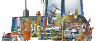
1937 Dodge Brothers coupe engine Six-cylinder GAZ-63 engine, right side 1 - place where the full-flow fine oil filter "DASFO" should be located 2 - inertia-oil air filter 3 - carburetor 4 - intake manifold 5 - exhaust manifold 6 - installation location pre-heater 7 - pipe for connecting the pre-heater 8 - pipe from the cabin heater 9 - location of the fuel and oil pumps (hard to see) 10 - water radiator 11 - pump (centrifugal pump) 12 - thermostat and outlet pipe to the radiator 13 - block head cylinders 14 - underhood lighting lamp 15 - ignition coil 16 - additional resistor 17 - relay regulator 18 - cable drive for radiator shutters 19 - steering column Six-cylinder GAZ-63 engine, left side 1 - lower pipe to the pump 2 - pump (centrifugal pump) 3 - thermostat and outlet pipe to the radiator 4 - oil filler neck 5 - DC generator 6 - water radiator 7 - steering mechanism 8 - steering column 9 - car horn 10 - ignition distributor-distributor 11 - vacuum ignition timing regulator 12 - starter 13 - pedal drive for turning on the starter 14 — drive from the gas pedal to the carburetor throttle valve 15 — cable drive for radiator shutters 16 — relay regulator 17 — additional resistor 18 — ignition coil 19 — full-flow plate coarse oil filter 20 — cabin heater valve and hose to it 21 and 22 - crankcase ventilation hoses 23 - cable drives for the carburetor air damper and “manual gas”
While modernizing the design of the M1, GAZ engineers came to the conclusion that the car needed a new engine - the reserves of the old one were almost exhausted. Andrei Lipgart faced a difficult choice - try to create an engine from scratch at the plant, or use a foreign development.
Having analyzed the designs of American engines, we found out that the best option is the six-cylinder lower valve Chrysler flathead https://en.wikipedia.org/wiki/Chrysler_flathead_engine, mistakenly called “Dodge-D5” after the name of the Dodge Series D5
, on which it was installed.
It was a time-tested design, dating back to 1928, that proved to be extremely durable and reliable. The engine developed a fairly large specific power for that time, 22-24 hp. hp/l (compared to 12-15 hp/l for GAZ-A and GAZ-M1). The most important technical innovations are replaceable bimetallic crankshaft bearing shells, a thermostat in the cooling system, 100% oil filtration, plug-in heat-resistant exhaust valve seats, a crankcase ventilation system, automatic ignition timing, oxidized pistons, and a floating oil receiver. Despite the relatively large length of the six-cylinder cast iron block, the dry weight of the Dodge D5 was 310 kg. Moreover, this engine was very technologically advanced; almost no non-ferrous metals were used for the manufacture of parts (with the exception of pistons). Compared to the GAZ-M, the American engine consumed 4-5% less fuel because it operated with a higher compression ratio and had a better organized workflow. When all the pros and cons of the Dodge-D5 were weighed, A. A. Lipgart insisted on allocating funds for the purchase of equipment. In 1937, Lipgart himself went to the USA.
While ordering equipment for the production of 6-cylinder engines, he simultaneously studied the technology of their manufacture.
Having quickly found his bearings, Lipgart made strict demands on both the technology and the equipment ordered, which subsequently ensured the high quality of GAZ “sixes” for many years [ source not specified 765 days
].
The lead designer of the project was Evgeny Agitov, deputy chief designer for engines. Redesigned by GAZ specialists, the Dodge-D5, converted, in addition, to metric dimensions, turned into the GAZ-11, and its modifications lived on the assembly line until the 90s (GAZ-52). The Dodge D5 had cylinders with a diameter of 3¼ inches (82.55 mm), a stroke of 43/8 inches (111.1 mm), and its displacement was 217.76 dm3 (3568 cm3). The same parameters for GAZ-11: cylinder diameter - 82 mm, piston stroke - 110 mm, working volume - 3485 cm3. The GAZ-11 was conceived in two versions: with a cast iron head (compression ratio - 5.6, power - 76 hp at 3400 rpm) and with an aluminum head (compression ratio - 6.5, power - 85 hp. at 3600 rpm).
Before the war, few such machines were made. Production of the M1 was resumed after the war, while preparations were underway for the release of the Victory. Compared to the American model, the oil system in the GAZ-11 was changed (with a floating oil receiver); in the camshaft drive, the chain drive was replaced by a gear drive (with a textolite driven wheel) modeled on the Chevrolet straight-6 General Motors engine.
In the summer of 1938, prototypes of the engine were tested on a stand, but when introduced into production, numerous technological difficulties arose and “childhood diseases” were revealed, the elimination of which continued until the war. The start of mass production of the engine had to be postponed to February 15, 1940 (128 serial engines were produced in 1940, in 1941-1451).
The senior engineer of the special group for aircraft engines was L. L. Zilpert. In the aviation modification of the GAZ-11, a gearbox was mounted instead of a gearbox; on the first prototypes, one K-23 type carburetor or two M-1 types were installed in the upper part of the engine.
In April 1939, a prototype of the ship modification was manufactured. After eliminating a number of “childhood diseases” by 1941, the design was finalized, and state tests took place between September 29 and October 16. GAZ-11 passed tests with the conclusion “can be adopted by the Navy.” Mass production of the ship modification was not mastered due to the need to increase the production of power plants for tanks.
During the war, engines were required for installation on tanks and self-propelled guns, so the GAZ-11 in its “pure” form was practically not produced during the war years (in small quantities it was used only on GAZ-61 cars and a small batch of GAZ-11-73, manufactured before June 1941), but after the war the improvement of the GAZ-11 was continued. As a result of modernization, GAZ-51, GAZ-12 and GAZ-52 engines appeared.
Adjusting the Gas 3307 and Gas 53 valves
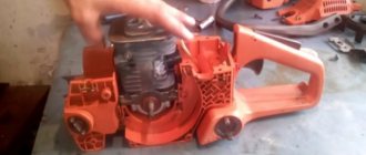
Hello dear friends! Today we will learn how to adjust valves. It would be more accurate to say that we will learn how to adjust the valves correctly. I will describe how I myself adjust the valves on ZMZ 511 engines. Actually, adjusting the valves: where they are adjusted in the usual way (by the term “usual method” I mean a wrench, a screwdriver and a feeler gauge) be it a Gazonchik, be it a Zil or an L engine /ah, yes, at least a diesel engine.
The valves are regulated approximately the same way, you just need to observe how many degrees to turn the crankshaft or camshaft. And necessarily the size of the gap; each engine has its own parameters. (There is even a difference between the intake and exhaust valves, but this is not so critical). I can’t help but say that there are still engines where the valve clearances are adjusted not with a feeler gauge, but with so-called nickels:
that is, the size of the required gap size is adjusted by the thickness of a suitable nickel. Nickels, as I think you guessed, come in different thicknesses and their thickness is measured using a micrometer - microns. So the dimensions are burned out with a laser on them, but it happens that the size is not visible, it is rubbed off, and this is where the micrometer comes to the rescue. This method of adjustment is not yet found on our domestic trucks (I can’t say anything about foreign cars, I don’t know). But on vehicles this method has been used for a long time since the first front-wheel drive VAZs began to be produced since then and is still used today. There is also one type of engine where our intervention is not required, that is, the valves do not need to be adjusted. The valve clearances are regulated by a special hydraulic compensator; or rather, there is no gap; it is compensated by a special hydraulic compensator.
The correct operation of hydraulic compensators depends directly on the oil pressure in the engine. But this is a separate topic, I’ll write about it someday, but not today, and I haven’t digressed much from the topic.
Adjusting valves on the ZMZ 511 engine!
First way!
And since I already said, I will describe how I regulate it myself. So far there have been no problems or complaints.
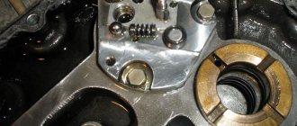
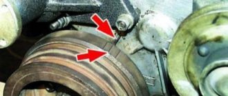
First of all, you need to open the valve cover and remove the rocker arms.
Why take it off, you ask, then to check if there is wear on the rocker arms. If the engine already has a lot of operating hours, then wear out on the rocker arms cannot be avoided. I indicated where the workings appear with an arrow in the picture.
The plane indicated in the picture should be exactly like this. If there is a waste, then you need to get rid of it. You need to clamp the rocker arms in a vice and use a flat file (rasp) to bring them to such a state that there are no developments. Otherwise you won't have any luck :). And so with each rocker. In this case, it is not necessary to remove the rocker arms from the rocker arm axis, as shown in the picture, you can align it, that is, get rid of the wear and tear in assembled form.
And so we aligned the rocker arms, got rid of the wear, now put the rocker arms in place and continue.
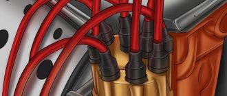
Now remove the ignition distributor (distributor) cover. In general, you can move the distributor cover with the spark plug wires to the side so that they don’t get in the way :). If you are suddenly afraid of getting confused with the order of connecting the high voltage wires from the distributor to the spark plugs, then you can read it, it’s all there. So put the wires with the distributor cap aside, they will only get in the way.
Installing the piston of the first cylinder at TDC.
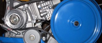
And now we need to set the piston of the first cylinder to TDC (Top Dead Center) and precisely in the compression stroke. How can we quickly find out exactly the compression stroke or not? We insert the handle for manual start, or whatever it is scientifically called (in some places it is a humpback, and in others it is crooked, I think you understand what I mean). And we turn it until the marks on the crankshaft pulley and in the front engine cover match:
A is a mark on the front cover of the engine, B, respectively, is a mark on the crankshaft pulley. Thus, we set the piston of the first cylinder to TDC.
And so, when these marks coincide, this does not mean that we can start adjusting; we still need to make sure that the compression stroke is exactly in the first cylinder. There are two simple ways:
- You need to unscrew the spark plug from the first cylinder and insert some kind of wad, preferably rubber, instead of the spark plug. And turn the handle until the marks coincide, and it is at the moment the marks coincide in the compression stroke that the wad will fly out, that is, the compression will simply blow it out. And this will be exactly the compression stroke.
- You can also check the compression stroke in a second way, faster than the above. After the marks on the pulley and the front cover match, the distributor slider should point backwards along the direction of the car. This will correspond to the fact that a spark is supplied to the first cylinder of the engine. And the spark is supplied precisely during the compression stroke (If the slider looks forward, this will be compression in the 6th cylinder). That is, I repeat once again: when you turn the engine with the handle, the slider also turns. If marks A and B coincide, the slider should look backward with its contact copper plate (backward along the direction of the car).
Now we have determined the TDC and compression stroke in the first cylinder and we can safely adjust the valves. Set the valve clearances to 0.30 mm and you won’t go wrong. 0.30 the feeler gauge should move with little effort, and 0.25 it should go through easily, then you will have an excellent gap, believe me, I always do this and recommend it to you. And so, after adjusting in the first cylinder, we turn the engine 90°, that is, a quarter turn, and adjust in the fifth cylinder, and so on, etc. Here's the order: 1-5-4-2-6-3-7-8.
Adjusting valves on the ZMZ 511 engine!
Second way!
I still can’t tell you that there is another way to adjust the valves. This is a “two-turn adjustment”, how do you understand this? Yes, very simple:
1. First, still set the piston of the first cylinder to TDC and precisely in the compression stroke. Then adjust the following valves:
- Intake valves of cylinders 1, 3, 7 and 8;
- Exhaust valves of cylinders 1, 2, 4 and 5.
2. Adjust the remaining valves after turning the crankshaft 360 degrees, that is, one revolution. And that is all.
The main thing to remember is that the valves must be adjusted when the engine is cold or no earlier than three hours after it has been turned off. And on summer and hot days even more. But if your car is parked on the street and you are adjusting it in winter, you need to start the engine and let it run for a while, 4-5 minutes will be enough, but no more.
It is also not recommended to adjust the valves on a completely cold engine, especially in winter.
Adjusting the Gas-66 valves on the ZMZ 511 engine!
When adjusting the valves of a Gas-66 with a ZMZ-511 engine, there is no difference, everything is the same as when adjusting the valves of a Gas-3307 and a Gas-53 with a ZMZ 511 engine.
But there is one point. There is simply a difference in the location of the marks on the pulley and the front engine cover. On the Gas-66, the marks are located not on the pulley and cover, but on the back of the flywheel and the casing (rear beam) of the engine. Everything else is exactly the same as on Gaz-3307 and Gaz-53. Here I took some pictures, in case anyone doesn’t know. Open the corresponding hatch on the rear beam of the engine, and you will see a mark and an arrow; everything is visible in the picture.
You can look at the order of operation of the cylinders here suddenly if you are afraid of making a mistake.
Well, let me finish here, today we adjusted the valves on the ZMZ 511.
If suddenly you haven’t found something, or you simply don’t have time to search, then I recommend reading the articles in the “GAS Repair” categories. I am sure you will find the answer to your question, and if not, write in the comments the question you are interested in, I will definitely answer.
To add comments you need to register
gaz3307.ru
Ignition system GAZ-52
The GAZ-52 ignition system consists of electrical energy sources, an ignition coil, an ignition distributor, spark plugs, wires and an ignition switch.
The primary circuit of the ignition system is powered by low voltage current from the generator or battery. Ignition coil B-115V-01 (Fig. 21) The ignition coil is installed on the engine and serves to convert low voltage to high voltage necessary to break down the spark gap in the spark plugs and ignite the working mixture in the engine cylinders. The ignition coil is a transformer, on an iron core 15 of which a secondary winding 11 is wound, and on top of it is a primary winding 10. Insulating spacers 13 are laid between the layers of the ignition coil winding. The core with windings is placed in a sealed steel housing 12 and secured in it with an insulator 14 and cover 2. The space between the coil, insulators and housing is filled with an insulating compound.
Rice. 21. Ignition coil GAZ-52 1 - high voltage clamp fitting; 2 - cover; 3 - high voltage terminal; 4 — contact spring; 5 - low voltage terminal; 6 - sealing gasket; 7 - magnetic circuit; 8 — fastening bracket; 9 - contact plate; 10 - primary winding; 11 - secondary winding; 12 — body; 13 — insulating gaskets; 14 - insulator; 15 — magnetic core; 16 - insulating filler; 17 — additional resistance insulator; 18 - additional resistance; 19 — bracket for additional resistance; 20 — screw for fastening additional resistance. Cover 2 has clamps for connecting wires. Between the legs of the coil mounting bracket there is an additional resistance 18 connected in series with the primary winding. Additional resistance is placed in a special insulator 17. When the starter is turned on, the additional resistance is short-circuited by additional contacts of the starter switch, as a result of which the current passing through the primary winding of the coil increases and the voltage in the secondary circuit increases. This ensures reliable ignition of the working mixture when starting the engine with the starter, when the battery voltage drops significantly due to the high current consumption of the starter. Malfunctions of the B-115V-01 ignition coil Malfunctions of the GAZ-52 ignition coil are associated mainly with damage to the insulation of its windings and their damage to additional resistance. Before removing the coil for repair or replacement, you should make sure that the wires are connected properly and securely to the terminals of the coil, ignition switch and starter, then check the ability of the spark to overcome the spark gap. Typical signs of damage to the additional resistance or its circuit are normal starting of the engine with the starter and its instant stop when the starter is turned off. A faulty auxiliary coil resistance should be repaired or replaced. If the cause of the malfunction is a broken contact or a wire break at the point where the ends are connected, then the wire in the indicated place must be carefully soldered. The burnt resistance must be replaced. If there is no spare resistance, it can be made from nickel wire of the NP-2 grade with a diameter of 0.3 mm. The GAZ-52 ignition coil with damaged winding insulation needs to be replaced.

When replacing a faulty ignition coil or damaged electrical wiring, you should carefully connect the wires to the coil terminals, since mixing up the wires can lead to damage to the coil and severe burning of the distributor breaker contacts. The low voltage wires are connected to the B115-V coil as follows: the wires from the short-circuit terminal of the ignition switch and from the terminal of the additional contacts of the ignition switch are connected to the B-VK terminal, the wire from the additional contacts of the starter switch is connected to the VK terminal, the wire from the starter switch is connected to the third terminal. distributor breaker. The high voltage wire from the distributor is connected to the high voltage terminal of the coil.
________________________________________________________________________________
Spare parts for Lviv loaders 4014, 40814, 40810, 4081, 41030 are shipped to all cities of Russia: Kemerovo, Ekaterinburg, Chelyabinsk, Novosibirsk, Ulan-Ude, Kirov, Perm, Krasnoyarsk, Irkutsk, Omsk, Barnaul, Tomsk, Bratsk, Tyumen , Lysva, Novokuznetsk, Miass, Serov, Chita, Berezovsky, Mezhdurechensk, Nizhny Tagil, Biysk, Minusinsk, Satka, Kurgan, Novy Urengoy, Norilsk, Noyabrsk, Oktyabrsky, Orenburg, Orsk, Prokopyevsk, Prokhladny, Pskov, Rubtsovsk, Rybinsk, Ryazan , Salavat, Saransk, Sarapul, Severodvinsk, Sibay, Sochi, Stavropol, Stary Oskol, Sterlitamak, Surgut, Syzran, Taganrog, Tambov, Tobolsk, Ust-Ilimsk, Ukhta, Khabarovsk, Khanty-Mansiysk, Chistopol, Chusovoy, Shadrinsk, Shakhty, Shelekhov, Elektrostal, Elista, Engels, Yakutsk, Vologda, Nizhny Novgorod, St. Petersburg, Belgorod, Orel, Kazan, Rostov-on-Don, Voronezh, Bryansk, Krasnodar, Saratov, Murmansk, Tula, Noginsk, Volgograd, Ivanovo, Penza , Cheboksary, Volzhsky, Yaroslavl, Syktyvkar, Izhevsk, Samara, Makhachkala, Volzhsk, Yoshkar-Ola, Sokol, Ufa, Arkhangelsk, Tver, Podolsk, Ulyanovsk, Smolensk, Togliatti, Vladikavkaz, Petrozavodsk, Kursk, Vladimir, Cherepovets, Naberezhnye Chelny and etc.