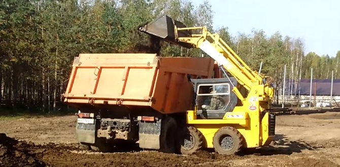
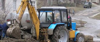
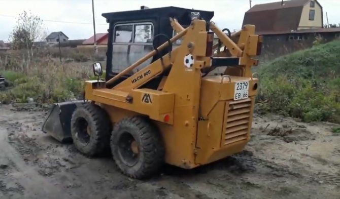
MKSM-800 is a small-sized mini-loader for performing various types of work from a Russian manufacturer. Special equipment is characterized by high reliability and performance.
The all-wheel drive chassis combined with a solid and flat bottom make this vehicle very passable. The “skidster” type of maneuvering (turning and turning) allows you to turn the machine almost on the spot. The fact is that control is carried out by rotating only one pair of wheels, while the other stands still.
However, it is the side turn that causes rapid tire wear. Several types of tires have been developed for the car. There are both the usual pneumatic ones, but with different types of frames, and solid rubber tires. The airless version is more suitable for use indoors and on flat, dry surfaces, due to the lack of chassis shock absorption on the loader. Also a plus will be the loader’s low load capacity. Additional equipment on the market is represented by more than 60 devices developed specifically for the MKSM platform.
Areas of application: construction
Due to its compactness and small size, MKSM-800 is used both indoors and on the construction site during low-rise construction. The range of peripheral equipment makes it truly universal and sometimes irreplaceable.
Here is a far from complete list of equipment used in general construction work:
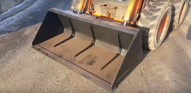
- Construction/industrial bucket.
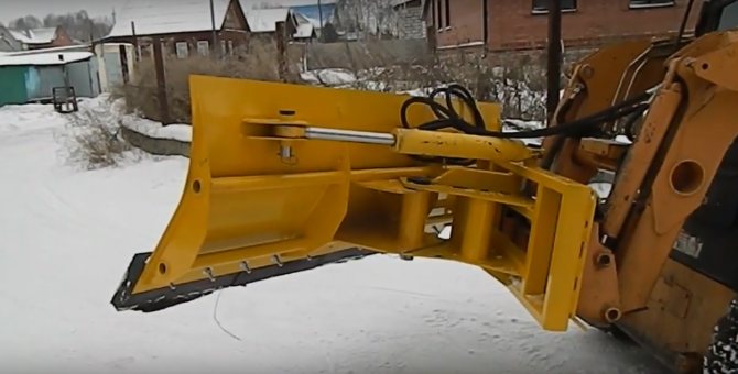
- Bulldozer blade.
- Double-jawed bucket.
- Pallet forks.
- Tipper bunker.
- Trencher.
![]()
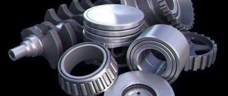
Repair of MKSM-800 loader in Moscow
If you do not have the spare parts you need or order non-standard products, delivery is carried out as quickly as possible. We ship spare parts by transport companies to the regions.
Detailed information on the availability of spare parts can be found in the sales department by phone. Repair of the MKSM-800 loader. Repair of the MKSM-800 loader is carried out by our mobile service department, which travels to the customer to diagnose and troubleshoot the MKSM front loader. Complex repairs are carried out on the service territory, where there are all the necessary conditions and the latest equipment that allows you to successfully perform a full range of services for the repair of a mini loader, test benches for hydraulic pumps and hydraulic motors MKRN, VMIZH, GST-33, SPV-20, MOTORPAL fuel equipment and injectors .
E}у╢Ф2;╤╣dЦ╘═ w╛ i╓╪<└;ЕУaTJ┌HаVOe╓V{╓┴┐Ё1╚SК└еУжBZ╟.└bqIИnNDьpbfljePZA/O~|z*ЯАИУC╓╧ P ┼▒ (╘#VRtss≈Xj!▌┤╖k┤PPT╞▐Я┤╖ n#2│vv:TSI╞T.├ъШ)└O)└Гб ·?ЦУГ. ▀шьм╧~De╕Yi╜й│С╛г╚sE▀ж█Un╓⌡_Ъ·7\т┼ ╩╡}▒L_Ц4j┘?ИРЪ║.А<«тC]8╣Z ё╨D! ▀ chYE≥╫ы$Ч▓\уJГТПжplЦr-VFCШ╞5к├┤кя1хИ╗╛ ╙х|koа^┴ы╫Y9mi≥zУYСЁН ÷ [email protected] ©ы╔Н;Ляг╚сrvS╛╬▐,■T∙ · =f╒tRL≈ХСкШ[9╕)7▌9фШО≥rAW<⌠EB²╞╖tгш=╖W█╤┤t(╒tшт≤ыh╫Р╣дVеw*┴VН┬bVV7ФыАпzХU╥╔е(lvk ▓▌ АОыm≥iuХ▒Б\УП╬Пу÷╟ннЦ║у МЧЭ]≥╔=2и6vc÷°╠цш≥nи╥╒V:СЦач{┼╨[&Ju хUаУвч [п{ш\БДЭзГ [email protected] ьы╨ ⌡┤#e│g▐╚╧z≤O,b=fuxh╗╠~#[yzh`┬N[zhGCpJEKHYUTSNO╓]mХp3▌╡[etyPzJ?┬⌡JУ(ъ+j╘╞╨[╪╥c# k╚Yua7┌G ╩B═▓│╙2╦z╧]Kы\╡6s╥Lsh╗Ё;i║═c╚^uB┐╞k┐M▌5╜UD7;╡p╤&_Q╖└╖g ▒7r##ЧЧьv!nУ║■GU║&}╨!©^D[╬|C┌%╬Ъ┤█ъ┘╪bЭД©lФ 'Р*y]╣и─Ш╣_┴╦чP╢ъ ".е6╒2в╕c╫Ф╝V ╬9 ЪУ╝ъwИЗ╫qWХ^╜13╦^∙EMYNyd]?Ъ$▓SUc9o∙ITs©ы╞rМ6bьГ+Tй┘ь░и<=wi\╩Ё] ьр╔н÷Д{цs≈┤ Ж▓ЭBI*╞d-H3┐│`b_YumShch┤▌$n) / KЁQSlЦК╜= ⌡°lГ╝ГДH┴qШ:╕Tзу┴!хч{Ё%≤╗РР&i╕ (JУз- dUк╝лЛ_.
MKSM-800 and utilities
The widespread use of this type of equipment in public utilities is determined by its reliability and efficiency. MKSM-800 can become indispensable when cleaning sidewalks and clearing them of snow. Caring for shrubs and lawns can also be included in the list of work performed. And of course this includes transportation and loading of various cargoes and bulk materials. Fuel consumption from 5 liters per hour. Ease of operation and availability of spare parts are also undeniable advantages.
Equipment options:
- Rotating brush.
- Long bristled brush (vertical).
- Snow plow.
- Rotary snow thrower.
- Brush cutter.
- Ladle.
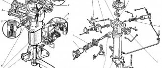
Operation of the MKSM-800 hydraulic system
When the engine of the MKSM 800 loader is running and the levers are in the neutral position, the pump of the working equipment takes the working fluid from the tank and delivers it through the pressure filter to the pressure section of the distributor.
When all distributor spools are in the neutral (middle) position, the primary safety and overflow valve of the pressure section of the distributor operates in overflow valve mode, connecting the pressure and drain hydraulic lines to each other.
As a result, the working fluid from the pressure section of the distributor enters the inlet of the drain filter and then to the suction cavities of the volumetric hydraulic drive feed pumps. When the pressure in the suction cavities of the make-up pumps reaches a pressure equal to the setting pressure of the tank valve, it opens and the excess working fluid is drained into the tank.
From the pressure output of each of the make-up pumps, the working fluid through the make-up valves enters the suction cavity of the corresponding axial piston pump.
When the pressure in the suction cavities of the pumps is equal to the setting pressure of the corresponding control valve, the valves open and the excess working fluid is drained into the hydraulic pump housings, from which it flows through the drainage hydraulic line into the radiator and drain filter into the tank.
When the radiator resistance is high, the valve opens and part of the working fluid is discharged into the tank, thereby limiting the pressure in the drainage hydraulic line, protecting the components from destruction. From the pressure output of one of the charging pumps, the working fluid is supplied to the brake and travel blocking valve, and from the pressure output of the second charging pump, the working fluid is supplied to the travel blocking valve and working equipment.
When the safety lever is raised, the valves move to the left. In this case, the valves disconnect the pressure outputs of the feed pumps from the corresponding control mechanisms of the hydraulic pumps of the volumetric hydraulic drive and connect the hydraulic lines of the control mechanisms of the hydraulic pumps, the drain hydraulic line to the tank.
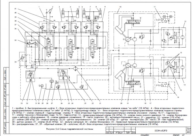
You can download the hydraulic system diagram here 4.pdf
As a result of this, the axial piston pumps of the positive displacement hydraulic drive are transferred to the idle operating mode, in which the pump performance is zero, regardless of the presence of action on the motion control lever. This prevents the machine from moving when the motion control lever is accidentally moved. In addition, the following valves are connected to the drain hydraulic line: the boosters of the vehicle’s parking brakes, which leads to its braking, and the distributor blocking valve. As a result of the latter, the primary safety and overflow valve of the pressure section of the distributor is switched to the overflow valve operating mode, regardless of the position of any of the distributor spools. This eliminates the possibility of lifting the boom and moving the bucket “toward itself” in case of accidental movement of the control lever of the working equipment.
When the safety lever is lowered, the valves move to the right. In this case, the valves connect the pressure outputs of the feed pumps with the corresponding control mechanisms of the hydraulic pumps of the volumetric hydraulic drive. In addition, the valve connects the pressure output of one of the charging pumps with the boosters for releasing the parking brakes of the machine, which leads to its release, and the other valve connects the pressure output of the second charging pump with the distributor blocking valve, which leads to the removal of the blocking mode of the working equipment.
When the motion control lever moves, the working fluid from the feed pumps through the distributors of the control mechanisms of the hydraulic pumps and volumetric hydraulic drive enters their control cylinders. This causes the performance of the corresponding axial piston pump to change from zero to a value determined by the movement of the motion control lever.
From the pumps, the working fluid flows to the hydraulic motors and returns to the corresponding pump, forming a closed circulation circuit of the working fluid. Safety valves are installed in the circuit to protect the pump and hydraulic motor from overload. Compensation for leaks of working fluid in the drain hydraulic line of the working fluid circulation circuit is provided by a make-up pump. The required pressure in the drain hydraulic line of the circuit is provided by a valve that is automatically connected to the drain hydraulic line by a distributor located in the valve box of the hydraulic motor. The valve opening pressure adjustment amount is less than the valve adjustment amount. The discharge of working fluid from the hydraulic drain line through the valve into the radiator ensures cooling of the working fluid and hydraulic machines. The speed and direction of movement of the machine is determined by the amount and direction of movement of the drive control lever from the neutral position.
When moving any of the distributor spools, using the work equipment control lever or the control pedal of replaceable attachments, the primary safety-overflow valve of the distributor is switched from the overflow valve operation mode to the operating mode, disconnecting the pressure hydraulic line from the drain line. From the pump of the work equipment through the pressure section of the distributor , check valve of the corresponding working section and its spool, the working fluid enters:
— when lifting the boom — into the piston cavities of the hydraulic cylinders;
— when moving the bucket “towards itself” - into the rod cavities of the hydraulic cylinders;
- when working with replaceable attachments - to the quick-release couplings, to the right one along the loader's path, when tilting the control pedal of the replaceable attachment forward forward, to the left - when tilting the pedal backwards.
From the opposite cavities of the actuators, the working fluid through the corresponding distributor spool and its pressure section enters the drain hydraulic line. When any of the spools moves from the neutral position and the pressure in the cavity of the actuator increases to a value equal to the setting of the primary safety overflow valve, the latter opens and the working fluid flows through it from the pressure hydraulic line to the drain.
This ensures protection of machine elements from overload. When the spools are in the neutral position, protection of the actuators from overload is ensured by secondary make-up and safety valves of the corresponding section, which, when opened, connect the cavity of the actuator with the drain hydraulic line. When a vacuum occurs in the cavities of the actuators, the check valves of the secondary make-up safety valves open and the working fluid flows from the drain hydraulic line into the indicated cavities.
Hydraulic system MKSM 800
Spare parts and repairs MKSM 800 MKSM1000
by phone +7 977 738 51 24
photo catalog of spare parts
Road construction
It is allowed to use a universal loader when constructing roads and sidewalks. Starting from soil development and ending with cleaning of the finished coating. Transportation of bulk materials, sand and crushed stone. Compacting before laying asphalt. Milling old asphalt concrete pavement. Supply of pallets with paving slabs. Cleaning sand after laying paving stones.
Other types of road construction work are possible using additional equipment. Such as:
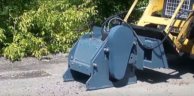
- Hydraulic hammer.
- Road milling cutter.
- Milling cutter for sewer manholes.
- Vibrating plate.
- Brush with hopper.
- Sand cleaner.
Specifications
| Name | MKSM-800A-1 |
| Engine | |
| Engine model | Cummins A2300 |
| Cooling system | liquid |
| Power, hp | 48 |
| Specific fuel consumption, g/kWh (g/hp) | 253 (186) |
| Fuel tank, l | 75 |
| Performance characteristics | |
| Maximum load capacity, kg | 800 |
| Maximum speed, km/h | 10 |
| Static tipping load, N (kgf) | 16000 (1600) |
| Hydraulic capacity, l/min | 75 |
| Boom lift | radial |
| Hydraulic equipment control drive type | mechanical |
| Operating time without refueling, hour | 8,5 |
| Pneumatic tires | 10,0/75-15,3 |
| Heater | autonomous |
| Temperature Range | from -40 to +45°С |
| Dimensions and weight | |
| Width with tires, mm | 1720 |
| Track width no more than, mm | 1450 |
| Ground clearance not less than, mm | 206 |
| Operating weight with main bucket, kg | 3170+2,5% |
Green building
Improvement of local areas, creation of parks and public gardens, landscape design.
A multi-purpose loader can do this. Soil development is possible using:
- Leveler planner.
- Dump.
- Grader.
Replanting and planting trees and shrubs. Laying turf on the prepared surface. It is possible to care for the lawn using a lawn mower and scarifier. Spraying and fertilizing will help produce various aerators and watering machines. Loosening and digging the earth. Drilling holes. All this is produced in the form of removable attachments and is unified with the MKSM models.
When working in a forest belt, devices such as:
- Log gripper.
- Rooter.
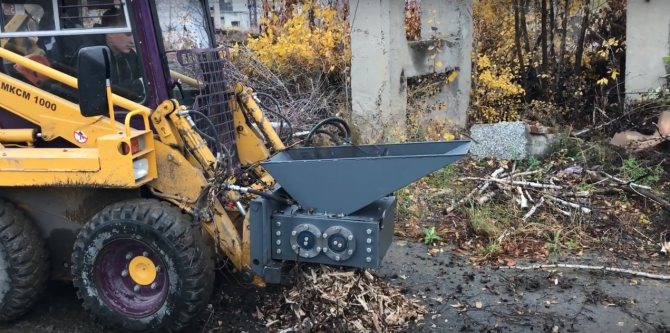
- Branch chopper.
- Stump grinder.
- Trimaxillary capture.
Agriculture
A mini loader is also indispensable in agriculture. For this purpose there are forks and a bale transporter. To work in adverse road conditions, be it mud or other unstable surfaces, there are special metal tracks. The tracks are put on over the wheels and significantly increase the stability and maneuverability of the vehicle.